
Service Manual
Refrigeration Details:
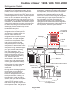
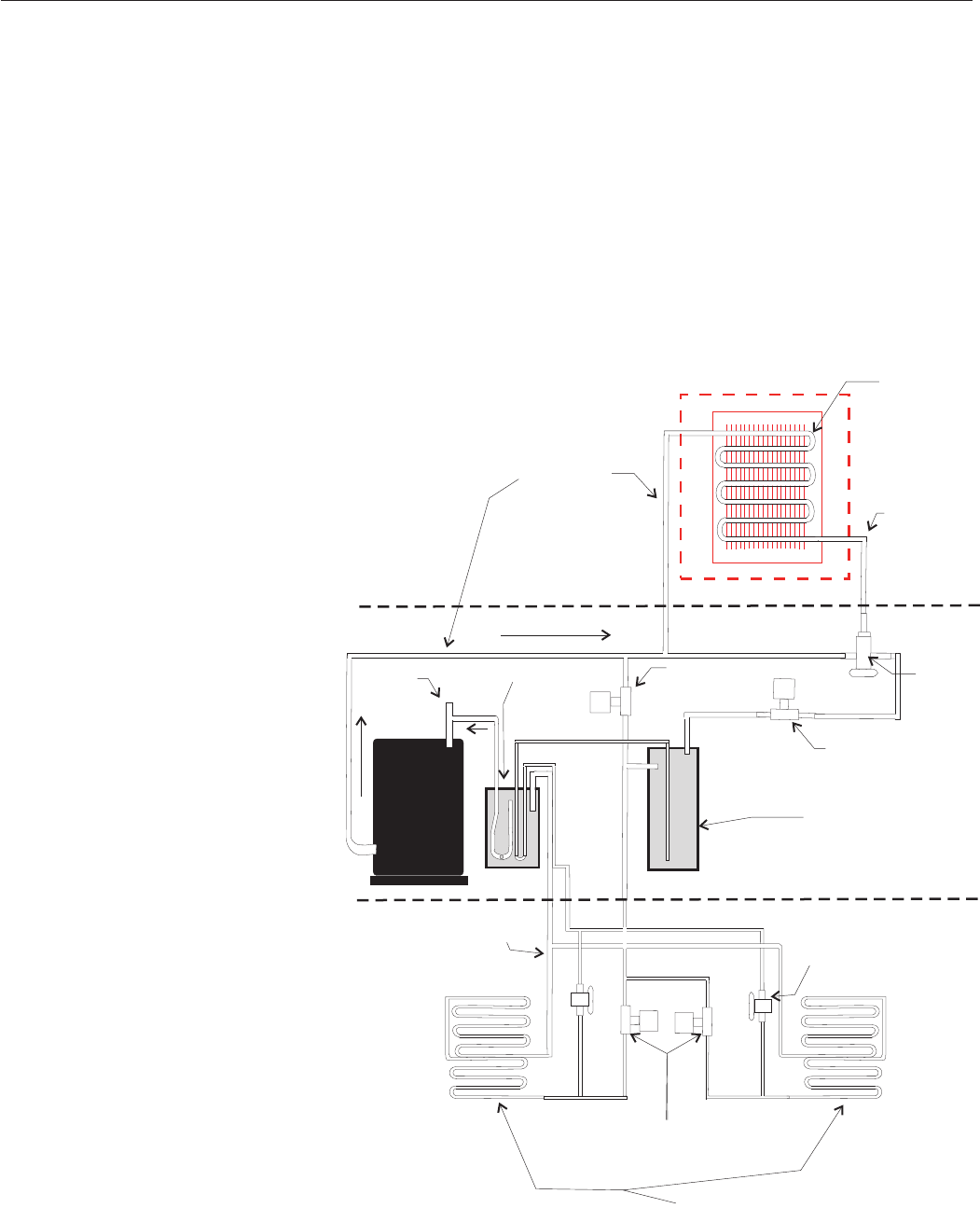
The compressor provides the force that circulates
refrigerant in the refrigeration system. During
freeze, when the vapor inlet and condenser by
pass valves are closed, discharge gas flows from
the compressor into the condenser, where its heat
is discharged into the air stream. Liquid refrigerant
flows out of the condenser and through the
normally open liquid line outlet valve on its way to
the receiver inlet. Under low ambient/low pressure
conditions, the headmaster valve closes the liquid
outlet of the condenser and opens a bypass route
to direct refrigerant gas to the receiver inlet until
discharge pressure builds back up to the
headmaster’s set point.
From the receiver liquid outlet, liquid
refrigerant flows into the liquid line
and into the ice making section. At
the ice making section, the
refrigerant flows into the expansion
valves where a pressure change
takes place. The liquid refrigerant
moves from the expansion valves
into a low-pressure area (the
evaporators) where it can rapidly
evaporate and absorb heat. Heat is
absorbed from the copper
evaporator tubing, attached copper,
pan, grid, and the water flowing
over the evaporators. The
low-pressure refrigerant gas then
flows into the suction line, which
carries it back to the condensing
unit, where it enters the
accumulator. In the accumulator
most of any liquid carried with the
suction gas is separated and only
vapor flows out of the accumulator
through the CPR valve and to the
compressor where the cycle
continues.
During harvest discharge gas flows
through the open condenser by
pass valve into the vapor line.
Power is also applied to the coil of
the liquid inlet valve, closing it. At
the same time, in the ice making
section, the vapor inlet valve opens.
Discharge gas, combined with some
vapor from the receiver’s outlet,
then flows through the vapor line to
the evaporator inlets. The gas-vapor
combination, when entering the relatively cold
evaporators, condenses, transferring latent heat to
the evaporators, which warms them. Ice releases
and falls into the bin. The low-pressure refrigerant
then flows out of the evaporators and into the
suction line. The suction line brings the refrigerant,
now consisting of a vapor-liquid combination, to
the accumulator. From the accumulator the
vapor-liquid combination (now more vapor than
liquid) goes to the Crankcase Pressure Regulator
valve which limits the amount of dome pressure in
the compressor, where the cycle continues.
Prodigy Eclipseä 1200, 1400, 1800, 2000
August 2008
Page 33
Discharge
Line
Headmaster
Liquid Inlet
Valve (N.O.)
By-Pass Valve
TXV
Vapor Inlet Valves
Evaporators
Receiver
Liquid
Line
CPR
Valve
Suction Line
Manifold
Accumulator
Air Cooled
Condenser
Coil
D
L
L
V
S