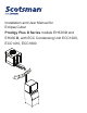
Installation and User Manual for Eclipse Cuber Prodigy Plus D Series models EH330 D and EH430 D, with ECC Condensing Unit ECC1200, ECC1410, ECC1800
EH330, EH430 D and ECC Condensing Unit Remote Low Side Cuber User Manual Introduction: This manual covers the assembly, installation, start up, operation and maintenance of the 1200, 1400 and 1800 remote low side cuber systems. Contents Configuration. . . . . . . . . . . . . . . . . . . . . . . . . . . . . . . . . . . . . . . . . . . . . . . . . . . . . . . . . . . . . . . . . . Page 2 Technical Specifications . . . . . . . . . . . . . . . . . . . . . . . . . . . . . . . . . . . . . . . . . . . . . . .
EH330, EH430 D and ECC Condensing Unit Remote Low Side Cuber User Manual Configuration A remote low side cuber system includes two sub systems: an ice head section and a remote condensing unit. Additionally, there are several models of each sub-system and this manual covers all of them. Warranty The ice making sections are designed for use indoors in a controlled environment. The remote condensing units are designed to operate outdoors. Each subsystem has limits for power, water and temperature.
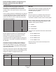
EH330, EH430 D and ECC Condensing Unit Remote Low Side Cuber User Manual Technical Specifications Model Electrical (volts/Hz/phase) EH330SL-1D EH430SL-1D ECC1200-32 ECC1410-3 ECC1410-32 115/60/1 115/60/1 208-230/60/1 208-230/60/3 208-230/60/1 Minimum Circuit Ampacity 3 3 17.8 9.1 14.5 ECC1800-3 208-230/60/3 19.0 * See Cabinet Drawings for exact dimensions. Maximum Fuse Size Cabinet Size* w” x d” x h” Approx.
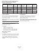
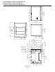
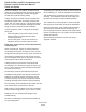
432.56 17.03 October 2014 Page 4 BACK VIEW 703.20 27.69 3/4" FPT DRAIN 3/8" FPT WATER INLET ELECTRICAL CORD ACCESS HOLE 88.62 3.49 69.32 2.73 448.56 17.66 INFERFACE CABLE ACCESS HOLE 56.64 2.23 313.69 12.35 381.76 15.03 609.60 24.00 38.23 1.51 UTILITY CASE 530.86 20.90 3/8" LIQUID LINE 1/2" COOL VAPOR LINE 3/4" SUCTION LINE 94.72 3.73 110.46 4.35 141.73 5.58 153.16 6.03 190.50 7.50 464.82 18.30 50.80 2.00 LEFT SIDE VIEW 609.60 24.00 PLAN VIEW ICE DROP OPENING 244.60 9.63 393.
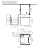
508.76 20.03 3/8" FPT WATER INLET October 2014 Page 5 BACK VIEW 703.58 27.70 3/4" FPT DRAIN ELECTRICAL CORD ACCESS HOLE 88.62 3.49 3/4" SUCTION LINE 533.62 21.01 INFERFACE CABLE ACCESS HOLE 600.71 23.65 681.74 26.84 3/8" LIQUID LINE 1/2" COOL VAPOR LINE 56.64 2.23 477.01 18.78 85.06 3.35 93.98 3.70 108.46 4.27 141.73 5.58 38.23 1.51 UTILITY CASE 216.15 8.51 228.60 9.00 609.60 24.00 464.82 18.30 50.80 2.00 244.60 9.63 ICE DROP OPENING LEFT SIDE VIEW 609.60 24.00 PLAN VIEW 393.
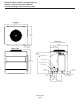
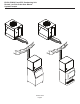
EH330, EH430 D and ECC Condensing Unit Remote Low Side Cuber User Manual Cabinet Drawings, ECC Condensing Unit TOP VIEW 992.81 39.09 814.22 32.06 SIDE VIEW LINE SET AND ELECTRICAL ATTACHMENT SIDE FRONT VIEW 32.05 1.26 TYP. 330.86 13.03 750.06 29.53 887.73 34.95 .88" ELECTRICAL INLET 1009.65 39.75 3/4" SUCTION LINE 1/2" COOL VAPOR LINE 3/8" LIQUID LINE 83.67 3.29 63.50 2.50 74.12 2.92 INTERFACE HARNESS ACCESS HOLE 163.02 6.42 248.87 9.80 October 2014 Page 6 491.69 19.
EH330, EH430 D and ECC Condensing Unit Remote Low Side Cuber User Manual Pre-Installation Details Water Note: The ice making head cannot be stacked vertically. Accessories such as bin adapters and tubing kits are required to complete the installation. Dispenser Adapter Kits: • Scotsman ID200 or ID250: KBT44 Bin Adapter Kits: • There are two ways water can contain impurities: in suspension or in solution. Suspended solids can be filtered out of the water.
EH330, EH430 D and ECC Condensing Unit Remote Low Side Cuber User Manual Create the System Plan the installation. The system consists of three parts: the ice making head, the condensing unit and the interconnecting tubing. Of these, the biggest variable is the interconnecting tubing. Tubing: The tubing consists of three insulated and sealed soft copper tubes. One tube, the liquid line, is 3/8” OD. The vapor tube is ½” OD and the suction tube is ¾” OD.
EH330, EH430 D and ECC Condensing Unit Remote Low Side Cuber User Manual System Example October 2014 Page 9
EH330, EH430 D and ECC Condensing Unit Remote Low Side Cuber User Manual Place Remote System Roof preparation Roof Pipe Curb or Pitch Pocket: Most installations of this system will place the condensing unit on the roof of a building. The roof must be physically able to accept the load of the equipment and the roofing material must be prepared to prevent water leaks. To avoid potential kinking of the refrigeration tubing, avoid small, tight radius types of covers on pitch pockets.
EH330, EH430 D and ECC Condensing Unit Remote Low Side Cuber User Manual Place Ice Making Head Remove from carton. Communication Cable Remove all panels. Plug the interconnecting communication cable into the harness at the back of the head unit’s electrical box. Utility Connection Route: Electrical: The unit is supplied with a power cord. There is also an interconnecting control wire that must be routed between the ice making head and the condensing unit.
EH330, EH430 D and ECC Condensing Unit Remote Low Side Cuber User Manual Condensing Unit Electrical Route interconnecting control wire through proper hole in side of CU unit and plug into the connection on the side of the control box. Route power conduit (liquid tight) and wires to the hole in the side of the CU unit. Connect to wire leads or terminal strip, if used, with the proper type of connector. Note: The power supply wires must be the correct size and type per the National Electric Code.
EH330, EH430 D and ECC Condensing Unit Remote Low Side Cuber User Manual Water and Drain All models require connection to cold, potable water. A hand actuated valve within sight of the machine is required. There is a single 3/8” FPT inlet water connection. Water Filters Install a new cartridge if the filters were used with a prior machine. All models require drain tubing to be attached to them. There is a single ¾” FPT drain fitting in the back of the cabinet.
EH330, EH430 D and ECC Condensing Unit Remote Low Side Cuber User Manual Connect Refrigeration Requires brazing, steps must be performed by an EPA certified type II or higher technician. At Head: 1. Remove protective plugs from all three connections and vent the nitrogen from the ice machine. 2. Route the each of the three tubes to its connection. At Head 1. With nitrogen flowing from condensing unit, braze the liquid, vapor and suction line connections. 2. Remove refrigeration hose from head.
EH330, EH430 D and ECC Condensing Unit Remote Low Side Cuber User Manual Complete the Installation After the utilities and refrigeration connections have been made, secure the unit to the dispenser or bin top. Open door to access On and Off switch buttons. Secure ice making section to dispenser or bin adapter. Use strap/clips to secure unit.
EH330, EH430 D and ECC Condensing Unit Remote Low Side Cuber User Manual Reference for Start Up: Controller Operation The controller has four indicator lights, a code display, four push buttons, and eleven component indicator lights.
EH330, EH430 D and ECC Condensing Unit Remote Low Side Cuber User Manual Initial Start Up Pre Start A soak-out period of four hours is optional for this system. If desired, powering the compressor unit for four hours prior to start up allows the crankcase heater to warm up the oil in the compressor. Start Up 1. Connect power to the condensing unit and move its toggle switch to Run or On. 2. Open the water supply valve. 3. Remove the head’s front panel. Check for any packing or wires rubbing moving parts.
EH330, EH430 D and ECC Condensing Unit Remote Low Side Cuber User Manual Ice Thickness and Water Purge Adjustment Bridge Thickness - For the Service Tech Only Small Depression 1. Push and hold Off till the machine stops. 2. Remove evaporator cover. 3. Remove left curtain. 4. Use a hex wrench and rotate the bridge thickness adjustment screw in 1/16 turn increments CW to increase bridge thickness. 5. Rotate CCW to decrease bridge thickness.
EH330, EH430 D and ECC Condensing Unit Remote Low Side Cuber User Manual Cleaning, Sanitation and Maintenance This ice system requires three types of maintenance: • Remove the build up of mineral scale from the ice machine’s water system and sensors. • • Sanitize the ice machine’s water system and the ice storage bin or dispenser. Clean the remote air cooled condenser. It is the User’s responsibility to keep the ice machine and ice storage bin in a sanitary condition.
EH330, EH430 D and ECC Condensing Unit Remote Low Side Cuber User Manual Step 13. Release probes by pushing in on white buttons and pulling probe down out of holder. Other Maintenance The remote air cooled condenser coil must be cleaned occasionally to keep the system operating at high efficiency. Airflow is from the outside in. Remove any large debris from the outside of the coil. Vacuum accumulated dust. Wash out the coils with water.
EH330, EH430 D and ECC Condensing Unit Remote Low Side Cuber User Manual Operational Characteristics 1200 lb system Cycle Times @ Condenser Temp/Cabinet Temp/Water Temp in degrees F. 70/70/50 90/90/70 Freeze 9 to 11 minutes 12 to 14 minutes Harvest 1 to 1.5 minutes 1 to 1.
EH330, EH430 D and ECC Condensing Unit Remote Low Side Cuber User Manual Operational Characteristics 1800 lb system Cycle Times @ Condenser Temp/Cabinet Temp/Water Temp in degrees F. 70/70/50 90/90/70 Freeze 10 to 14 minutes 12 to 16 minutes Harvest 1 to 1.5 minutes 1 to 1.
EH330, EH430 D and ECC Condensing Unit Remote Low Side Cuber User Manual What to do before calling for service: Reasons the machine might shut itself off: • • • • • Lack of water. Freeze cycle takes too long. Harvest cycle takes too long. High discharge pressure. Ice level control set wrong Check the following: 1. Has the water supply to the ice machine or building been shut off? If yes, the ice machine will automatically restart within 25 minutes after water begins to flow to it. 2.
EH330, EH430 D and ECC Condensing Unit Remote Low Side Cuber User Manual EH330 or EH430 Schematic Diagram October 2014 Page 24
EH330, EH430 D and ECC Condensing Unit Remote Low Side Cuber User Manual EH330 or EH430 Wiring Diagram October 2014 Page 25
EH330, EH430 D and ECC Condensing Unit Remote Low Side Cuber User Manual ECC 3 Phase Schematic Diagram October 2014 Page 26
EH330, EH430 D and ECC Condensing Unit Remote Low Side Cuber User Manual ECC 3 Phase Wiring Diagram October 2014 Page 27
EH330, EH430 D and ECC Condensing Unit Remote Low Side Cuber User Manual ECC 1 Phase Schematic Diagram October 2014 Page 28
EH330, EH430 D and ECC Condensing Unit Remote Low Side Cuber User Manual ECC 1 Phase Wiring Diagram October 2014 Page 29
SCOTSMAN ICE SYSTEMS 775 Corporate Woods Parkway Vernon Hills, IL 60061 www.scotsman-ice.