
Service Manual

N0422, F0522, N0622, F0822, N0922, F1222, N1322, F1522
Air, Water or Remote Service Manual
December 2014
Page 53
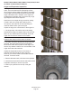
Repair Procedures: Replace the Evaporator:
(Assuming all the steps for removal of the thrust
bearing, breaker, auger, and water seal have been
performed.)
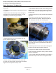
1. Recover the refrigerant from the ice maker.
2. Unsweat the refrigerant connections:
a) At the thermostatic expansion valve outlet.
Heat sink the TXV body when unsweating or
resweating the adjacent tubing.
b) At the suction line at the joint about 3" from the
evaporator.
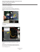
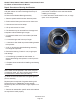
3. Remove the evaporator.
4. Unsweat the drier from the liquid line.
5. After installing a new water seal in the new
evaporator (see “To Replace the Water Seal”) sweat
in the new evaporator at the old tubing connections.
6. Install an new drier in the liquid line.
7. Evacuate the system until dehydrated, then weigh
in the nameplate charge. Check for leaks.
8. Install auger, breaker, breaker bearing assembly,
and ice discharge chute in reverse order of
disassembly.
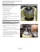
To Reassemble the Evaporator and Auger
1. After the gear reducer has been inspected, fasten
the evaporator to the gear reducer. Torque the bolts to
110 inch pounds.
2. Lower the auger into the evaporator barrel, slightly
turning it to match up with the drive end. Do Not Drop
Into the Evaporator.
3. Complete the reassembly by reversing the
disassembly for the breaker & thrust bearing
assembly.
Repair Procedures: Thermostatic Expansion Valve
1. Remove front panel.
2. If the machine was in operation, push and release
the off button to shut it down.
3. Disconnect electrical power.
4. Recover refrigerant.
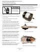
5. Remove insulation covering expansion valve and
bulb.
6. Remove strap securing bulb to suction line.
7. Unsweat the expansion valve from the liquid line.
Remove it.
8. Unsweat the drier from the liquid line. Remove it.
9. Connect nitrogen to discharge access valve.
10. Immediately place new valve in ice machine.
11. Open nitrogen bottle and braze expansion valve
inlet and outlet joints together. Braze new drier
into system.
12. Shut off nitrogen, shut access valves.
13. Evacuate to at least 300 microns.
14. Weigh in the nameplate charge. Check for leaks.
15. Attach bulb to suction line. Position at 4 or 8
o'clock on the tube. Secure tightly but do not crush
the bulb with the strap.
16. Attach valve and bulb insulation.
17. Reconnect electrical power.
18. Return all panels to their original positions.