TM Media Mantel With 26-IN Infrared Electric Fireplace ASSEMBLY, CARE & USE INSTRUCTIONS MODEL # 1167FMM-26-200; 1167FMM-26-201; 1167FMM-26-202 ITEM # 0849093;0849094;0849095 Date Purchased _______________________ Questions, problems, missing parts? Before returning to your retailer, call our customer service department at 1-855-571-1044 9 a.m. - 5 p.m., EST, Monday - Friday. www.greentouchhome.com Français p. 21 Español p.
PACKAGE CONTENTS A C M L E G D I N B P J M Q H N K F R S T O Q PART A B C D E F G H I J DESCRIPTION Top Left Corner Panel Right Corner Panel Center Shelf Partition Left Wall Right Wall Left Side Panel Right Side Panel Center Front Panel QUANTITY 1 1 1 1 1 1 PART 1 1 1 1 K L M N O P 2 DESCRIPTION Base Center Back Panel Side Back Panel Wood Shelf Left Front Door QUANTITY 1 1 2 Right Front Door 2 1 1 Q R S Wood Door Panel Insert Remote Control 2 1 1 T Battery 2
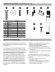
HARDWARE CONTENTS AA BB PART DESCRIPTION AA Long Bolt BB Washer CC DD EE FF GG Wooden Dowel Back Panel Screw Shelf Pin HH II (NOT SHOWN ACTUAL SIZE) CC DD QUANTITY 30 Insert Bracket Short Bolt Screw Touch-up Pen 30 26 38 8 2 EE FF GG HH II 6 4 1 SAFETY INFORMATION Please read and understand this entire manual before attempting to assemble, operate or install the product.
SAFETY INFORMATION (CONT’D) s Modifications not approved by the party responsible for compliance could void user’s authority to operate the equipment. This Class B digital apparatus complies with Canadian ICES-003. IMPORTANT INSTRUCTIONS s When using electrical appliances, basic precautions should always be followed to reduce the risk of fire, electric shock and injury to persons, including the following: s s s s s s s DANGER Read all instructions before using this heater.
SAFETY INFORMATION s s s s s (CONT’D) To prevent a possible fire, DO NOT block air intakes or exhaust in any manner. DO NOT use on soft surfaces, like a bed, where opening may become blocked. The heaters MUST NOT be located immediately below a socket-outlet. ALWAYS plug heaters directly into a wall outlet/receptacle. NEVER use with an extension cord or re-loadable power tap (outlet / power strip). DO NOT slide insert on top of wood to avoid scratching wood surface.
PREPARATION Estimated Assembly Time: 50 minutes Before beginning assembly of product, make sure all parts are present. Compare parts with package contents list and hardware contents list. If any part is missing or damaged, do not attempt to assemble the product. Tools Required for Assembly (not included): Phillips screwdriver ASSEMBLY INSTRUCTIONS 1. From behind the assembly, insert two wooden dowels (CC) into holes on left outer side of base (K).
ASSEMBLY INSTRUCTIONS (CONT’D) 3. Insert two wooden dowels (CC) into the top middle holes on both left side panel (H) and right side panel (I). Carefully position the center front panel (J) into place between left side panel (H) and right side panel (I). Secure each side with one washer (BB) and one long bolt (AA). 3 J CC 1 Hardware Used AA Long Bolt x2 BB Washer x2 CC Wooden dowel x2 4.
ASSEMBLY INSTRUCTIONS (CONT’D) 6. Insert two wooden dowels (CC) into holes on the middle of Center shelf (D ). Attach Partition (E), securing from underneath with one washer (BB) and one long bolt (AA). 6 CC Hardware Used E 1 AA Long Bolt x1 BB Washer x1 CC Wooden dowel BB AA x2 2 7. Insert two wooden dowels (CC) into the top outer holes of Partition (E). Attach top (A), securing from underneath with five washers (BB) and five long bolts (AA).
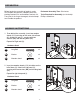
ASSEMBLY INSTRUCTIONS (CONT’D) 9. Attach side back panel (M) to shelving areas using back panel screws (DD). Repeat for remaining back panel (M). 9 DD 1 Hardware Used DD Back Panel Screw 1 x 20 2 10 N 2 10. From Front the assembly, insert shelf pins (EE) at desired height, ensuring they are level. Place shelf (N) on top of shelf pins (EE). Repeat for remaining the shelf (N). M M Hardware Used x8 11. Hold the door and align the hinge body with the hinge plate mounted to the fireplace wall.
ASSEMBLY INSTRUCTIONS (CONT’D) 12. If you need to adjust the doors, do so in the following manner. To adjust door up or down, loosen screws (a) on both hinges, adjust door, and retighten screws. To adjust door left or right, turn screws (b) on both hinges, in or out. To adjust door in or out, loosen screws (c) on both hinges, adjust door, and retighten screws. 12 2 2 2 2 2 2 a 1 a 3 1 1 1 b 13.
ASSEMBLY INSTRUCTIONS (CONT’D) 14. From behind the assembly, with the help of another person, position the insert (R) into opening of mantel assembly. 14 Note: DO NOT plug the insert (R) into power outlet yet. CAUTION: DO NOT slide the insert on top of wood to avoid scratching wood surface. R 15. Secure the insert (R) to the base (K) with two screws (HH) on the left side and on the right side of the insert (R).
CHANGE DOOR PANELS (OPTIONAL) Note: The pre-installed glass door panels can be switched out with the included wood door panel (Q). 1. Remove the silicone trim along the outer edges of the glass panel on the inside of the door. Start at a corner and pull to remove the four pieces. Be careful not to damage the silicone trim as it will be used to secure the new panel. 2. Remove the glass panel from the door frame, then insert the included wood door panel (Q). 3.
OPERATING INSTRUCTIONS Control Panel M Remote Control To use the remote control, first insert two AAA batteries (included) into the remote control. ensuring the polarities of the battery match the inside of the battery compartment. 8:88 Note: The control panel is a touch screen. It will appear black. Touch the control panel once to “wake up” the controls. This will cause the controls to light up. Which ever icon you touch will display it’s last setting when you do this.
OPERATING INSTRUCTIONS (CONT’D) Timer Function Press the TIMER ICON to set the countdown for the unit’s main power. If the unit is powered OFF, you can press the TIMER ICON to power ON the unit. The emberbed will glow at the lowest brightness setting unless a different setting was saved in the memory. Press the TIMER ICON again to scroll through the timer settings, which are: 30, 1h, 2h, 3h, 4h, 5h, 6h, 7h, 8h, 9h, OFF.
CARE AND MAINTENANCE • Make sure the unit is turned OFF, unplugged and the heating elements of heater are cool whenever you are cleaning the heater or fireplace. • Clean the metal trim using a water-dampened soft, clean cloth. DO NOT use brass polish or household cleaners as these products will damage the metal trim. • The motors used on the fan and the flame generator assembly are pre-lubricated for extended bearing life and require no further lubrication.
TROUBLESHOOTING PROBLEM POSSIBLE CAUSE CORRECTIVE ACTION Error E1 displayed on control panel. The overheat sensor has been engaged. Unplug unit, wait 15-20 minutes, then the sensor will reset itself. Plug the unit back in and turn on the heater. If the problem persists, call customer service. Note: The other functions will work normally excluding the heater. Until the problem is solved, the error will only appear/sound when the heater button is pressed. Error E2 displayed on control panel.
ONE-YEAR LIMITED WARRANTY The manufacturer warrants that your new Electric fireplace is free from manufacturing and material defects for a period of one year from date of purchase, subject to the following conditions and limitations. Install and operate this Electric fireplace in accordance with the installation and operating instructions furnished with the product at all times. Any unauthorized repair, alteration, willful abuse, accident, or misuse of the product shall nullify this warranty.
REPLACEMENT PARTS FOR 1167FMM-26-200 For replacement parts, call our customer service department at 1-855-571-1044, 9 a.m. - 5 p.m., EST, Monday - Friday. JJ LL KK O N P Q Item/Article/Artículo #0839834; 0849089; 0849090; 0849093;0849094;0849095 TM Model/Modèle/Modelo #1167FMM-23-200; 1167FMM-26-200 1167FMM-23-201; 1167FMM-26-201 1167FMM-23-202; 1167FMM-26-202 SCOTT LIVING and logo are trademarks of Scott Brothers Entertainment Inc. in the United State of America and elsewhere.
REPLACEMENT PARTS FOR 1167FMM-26-201 For replacement parts, call our customer service department at 1-855-571-1044, 9 a.m. - 5 p.m., EST, Monday - Friday. JJ LL KK O N P Q Item/Article/Artículo #0839834; 0849089; 0849090; 0849093;0849094;0849095 TM Model/Modèle/Modelo #1167FMM-23-200; 1167FMM-26-200 1167FMM-23-201; 1167FMM-26-201 1167FMM-23-202; 1167FMM-26-202 SCOTT LIVING and logo are trademarks of Scott Brothers Entertainment Inc. in the United State of America and elsewhere.
REPLACEMENT PARTS FOR 1167FMM-26-202 For replacement parts, call our customer service department at 1-855-571-1044, 9 a.m. - 5 p.m., EST, Monday - Friday. JJ LL KK O N P Q Item/Article/Artículo #0839834; 0849089; 0849090; 0849093;0849094;0849095 TM Model/Modèle/Modelo #1167FMM-23-200; 1167FMM-26-200 1167FMM-23-201; 1167FMM-26-201 1167FMM-23-202; 1167FMM-26-202 SCOTT LIVING and logo are trademarks of Scott Brothers Entertainment Inc. in the United State of America and elsewhere.
TM Meuble multimédia avec cheminée électrique infrarouge 26-IN English p. 1 Español p. 42 INSTRUCTIONS D’UTILISATION, D’ASSEMBLAGE ET DE MAINTENANCE MODÈLE # 1167FMM-26-200; 1167FMM-26-201; 1167FMM-26-202 ARTICLE # 0849093;0849094;0849095 Date d’achat _______________________ Des questions, des problèmes, des pièces manquantes? Avant de retourner l’article au détaillant, appelez notre service à la clientèle au 1-855-571-1044, entre 9 h et 17 h (HNE), du lundi au vendredi. www.greentouchhome.
CONTENU DE L’EMBALLAGE A C M L E G D N I B P J M Q H N K F R S T O Q PIÈCE A B C D E F G H I J DESCRIPTION Sommet QUANTITÉ 1 Panneau Coin Gauche 1 Panneau Coin Droit 1 1 Tablette Centrale Partition 1 Mur Gauche 1 Mur Droit 1 Panneau Côté Gauche Panneau Côté Droit Panneau Avant Central PIÈCE DESCRIPTION K Base L Panneau Arrière Central M Panneau Arrière Latéral N Tablette De Bois O Porte Avant Gauche P Porte Avant Droite 1 1 1 22 Q R S Panneau De Porte En Bois Insertion Télécommand
CONTENUS MATÉRIELS AA (NON REPRÉSENTÉS EN TAILLE RÉELLE) BB PIÈCE DESCRIPTION AA Boulon Long BB Rondelle CC DD EE FF GG Goujon De Bois Vis Panneau Arrière Cheville De Tablette HH II CC DD QUANTITÉ 30 Support De L'insertion Boulon Court Vis Stylo De Retouche 30 26 38 8 2 EE FF GG HH II 6 4 1 CONSIGNES DE SÉCURITÉ Assurez-vous de lire et de comprendre l’intégralité s RÏORIENTER OU DÏPLACER L ANTENNE RÏCEPTRICE du présent manuel avant de tenter d’assembler, s accroître la distance entre l’
CONSIGNES DE SÉCURITÉFETY (SUITE) • N’insérez JAMAIS un objet, quel qu’il soit, dans les ouvertures de ventilation ou de sortie d’air de par la partie responsable de la conformité peuvent annuler le droit de l’utilisateur de se servir de cet appareil. que les risques de choc électrique et d’incendie. • Cet appareil renferme des pièces chaudes qui produisent des arcs électriques ou des étincelles.
CONSIGNES DE SÉCURITÉ (SUITE) s "RANCHEZ UNIQUEMENT CORRECTEMENT MISE Ì LA TERRE s ,ORS DE L INSTALLATION VEILLEZ Ì CE QUE L APPAREIL SOIT MIS Ì LA TERRE CONFORMÏMENT AUX CODES LOCAUX Ì LA PLUS RÏCENTE VERSION DU #ODE CANADIEN DE L ÏLECTRICITÏ #3A # OU DANS LE CAS DES INSTALLATIONS AUX ³TATS 5NIS AUX CODES LOCAUX ET AU CODE NATIONAL DE L ÏLECTRICITÏ !.3) NFPA .O s BLOQUEZ JAMAIS LES OUVERTURES DE VENTILATION OU DE SORTIE D AIR DE QUELQUE FA ON QUE CE SOIT .
PRÉPARATION Temps d’assemblage approximatif : 50 minutes. Avant de commencer l’assemblage de l’article, assurez-vous d’avoir toutes les pièces. Comparez le contenu de l’emballage avec la liste des pièces et celle de la quincaillerie incluse. S’il y a des pièces manquantes ou endommagées, ne tentez pas d’assembler l’article. Outil nécessaire pour l’assemblage (non inclus) : tournevis cruciforme. INSTRUCTIONS POUR L’ASSEMBLAGE 1.
INSTRUCTIONS POUR L’ASSEMBLAGE (SUITE) 3. Insérez deux chevilles en bois (CC) dans les trous du sommet du milieu du panneau latéral gauche (H) et du panneau latéral droit (I). Positionnez attentivement le panneau central (J) entre le panneau latéral gauche (H) et le panneau latéral droit (I). Fixez chaque côté avec une rondelle (BB) et un long boulon (AA). QUINCAILLERIE UTILISÉE AA Boulon Long x2 BB Rondelle x2 CC Groujon En Bois 3 J CC 1 BB H AA 2 x2 4.
INSTRUCTIONS POUR L’ASSEMBLAGE (SUITE) 6. Insérez deux chevilles en bois (CC) dans les trous au milieu du centre de la tablette centrale (D). Fixez la partition (E) avec une rondelle (BB) et un long boulon (AA). 6 CC QUINCAILLERIE UTILISÉE E 1 AA Boulon Long x1 BB Rondelle x1 CC Goujon De Bois x2 BB AA 2 7. Insérez deux chevilles en bois (CC) dans les trous du sommet extérieurs de la partition (E). Fixez le sommet (A) en fixant à partir du dessous avec cinq rondelles (BB) et boulons (AA).
INSTRUCTIONS POUR L’ASSEMBLAGE (SUITE) 9. Fixez le panneau arrière latéral (M) aux zones des tablettes à l'aide des vis de panneau arrière (DD). 9 DD Répétez pour le panneau arrière restant (M). 1 QUINCAILLERIE UTILISÉE DD Vis Panneau Arrière 1 x 20 10. À partir du devant de l'assemblage, insérez les chevilles de tablette (EE) à la hauteur désirée, en vous assurant qu'elles sont au niveau. Placez la tablette (N) par dessus les chevilles de tablette (EE).
INSTRUCTIONS POUR L’ASSEMBLAGE (SUITE) 12. Suivez les étapes suivantes pour ajuster les portes. Pour ajuster la porte verticalement, desserrez les vis (a) sur les deux charnières, ajustez la porte et resserrez les vis. Pour ajuster la porte vers la gauche ou vers la droite, tournez les vis (b) sur les deux charnières vers l’intérieur ou l’extérieur. Pour ajuster la porte vers l’intérieur ou l’extérieur, desserrez les vis (c) sur les deux charnières, ajustez la porte et resserrez les vis.
INSTRUCTIONS POUR L’ASSEMBLAGE (SUITE) 14. À partir de l'arrière de l'assemblage, avec l'aide d'une autre personne, positionnez le poêle (R) dans l'ouverture de l'assemblage de la cheminée. 14 Note : NE branchez PAS le poêle (R) dans une prise d'alimentation. MISE EN GARDE: NE glissez PAS le poêle sur le dessus du bois pour éviter d'égratigner la surface de bois. 15. Fixez le poêle (R) à la base (K) avec deux vis sur le côté gauche et sur le côté droit du poêle (R). L'assemblage est maintenant terminé.
CHANGER LES PANNEAUX DE PORTE (OPTIONNEL) Note: Les panneaux de portes en verre pré-installés peuvent être changés pour le panneau de porte en bois inclus (Q). 1. Retirez la bordure de silicone le long des bords extérieurs du panneau de verre à l'intérieur de la porte. Commencez dans un coin et tirez pour enlever les quatre morceaux. Faites attention de ne pas endommager la bordure de silicone, car elle sera utilisée pour fixer le nouveau panneau. 2.
MODE D’EMPLOI Panneau De Contrôle M Télécommande Pour utiliser la télécommande, i nsérez d'abord deux piles AAA (incluses) dans la télécommande, en vous assurant que la polarité des piles corresponde à l'intérieur du compartiment des piles. 8:88 Note : Le panneau de contrôle est un écran tactile. Il apparaîtra noir. Touchez le panneau de contrôle une fois pour « réveiller » les contrôles. Cela allumera les contrôles. L'icône que vous toucherez affichera son dernier réglage lorsque vous faites cela.
MODE D’EMPLOI (SUITE) Fonction Minuterie s Appuyez sur l'ICÔNE MINUTERIE (TIMER) pour configurer un décompte pour l'alimentation de l'unité. s Si l'unité est éteinte, vous pouvez appuyer sur l'ICÔNE MINUTERIE (TIMER) pour allumer l'unité. Le lit de braise rougira à sa luminosité la plus faible sauf si un réglage différent a été enregistré dans la mémoire.
ENTRETIEN • Assurez-vous que l'appareil est ÉTEINT, débranché et que les éléments chauffants de l'appareil de chauffage sont froids lorsque vous nettoyez l'appareil de chauf • Nettoyez la garniture métallique à l’aide d’un linge doux légèrement humecté. N’utilisez PAS de produits pour polir le laiton ni de nettoyants à usage domestique, car ces produits endommageront la garniture métallique.
DÉPANNAGE PROBLÈME Le panneau de message « Error E1 » (erreur E1). Le panneau de message « Error E2 » (erreur E2). Le panneau de message « Error E3 » (erreur E3). CAUSE POSSIBLE Le détecteur de surchauffe s’est déclenché. MESURE CORRECTIVE Débranchez l’appareil et attendez de 15 à 20 minutes; le détecteur se réinitialisera. Rebranchez l’appareil et allumez le radiateur. Si le problème persiste, communiquez avec le service à la clientèle.
DÉPANNAGE PROBLÈME La télécommande ne fonctionne pas. CAUSE POSSIBLE MESURE CORRECTIVE La pile est faible ou Replacer avec 2 piles AAA. défectueuse. (Voir page 35 pour plus d'information.) Le signal de la télécommande est faible et ne fonctionne pas toujours bien. Vous appuyez trop rapidement sur les boutons. Vous utilisez la télécommande d’un endroit trop éloigné ou de biais. Le moteur du ventilateur continue de fonctionner après la mise hors tension de l’appareil. Fonctionnement normal.
GARANTIE Cet article est garanti par le fabricant contre les défauts de matériaux et de fabrication pour une période de un an à compter de la date d’achat. La présente garantie est assujettie aux restrictions et aux conditions suivantes : Ce meuble doit être installé et utilisé conformément aux instructions pour l’installation fournies avec volontaire ou tout usage inapproprié de l’article invalidera cette garantie.
LISTE DES PIÈCES DE RECHANGE 1167FMM-26-200 Pour obtenir des pièces de rechange, communiquez avec notre service à la clientèle au 1-855-571-1044, entre 9 h et 17 h (HNE), du lundi au vendredi. JJ LL KK O N P Q Item/Article/Artículo #0839834; 0849089; 0849090; 0849093;0849094;0849095 TM Model/Modèle/Modelo #1167FMM-23-200; 1167FMM-26-200 1167FMM-23-201; 1167FMM-26-201 1167FMM-23-202; 1167FMM-26-202 SCOTT LIVING and logo are trademarks of Scott Brothers Entertainment Inc.
LISTE DES PIÈCES DE RECHANGE 1167FMM-26-201 Pour obtenir des pièces de rechange, communiquez avec notre service à la clientèle au 1-855-571-1044, entre 9 h et 17 h (HNE), du lundi au vendredi. JJ LL KK O N P Q Item/Article/Artículo #0839834; 0849089; 0849090; 0849093;0849094;0849095 TM Model/Modèle/Modelo #1167FMM-23-200; 1167FMM-26-200 1167FMM-23-201; 1167FMM-26-201 1167FMM-23-202; 1167FMM-26-202 SCOTT LIVING and logo are trademarks of Scott Brothers Entertainment Inc.
LISTE DES PIÈCES DE RECHANGE 1167FMM-26-202 Pour obtenir des pièces de rechange, communiquez avec notre service à la clientèle au 1-855-571-1044, entre 9 h et 17 h (HNE), du lundi au vendredi. JJ LL KK O N P Q Item/Article/Artículo #0839834; 0849089; 0849090; 0849093;0849094;0849095 TM Model/Modèle/Modelo #1167FMM-23-200; 1167FMM-26-200 1167FMM-23-201; 1167FMM-26-201 1167FMM-23-202; 1167FMM-26-202 SCOTT LIVING and logo are trademarks of Scott Brothers Entertainment Inc.
TM Repisa de chimenea de información con hogar eléctrico infrarrojo de 26-IN English p. 1 Français p. 21 INSTRUCCIONES DE ENSAMBLAJE, CUIDADO Y USO MODELO # 1167FMM-26-200; 1167FMM-26-201; 1167FMM-26-202 ARTÍCULO # 0849093;0849094;0849095 Fecha de compra _______________________ ¿Preguntas, problemas, piezas faltantes? Antes de volver a la tienda, llame a nuestro Departamento de Servicio al Cliente al 1-855-571-1044 de lunes a viernes de 9:00 a.m. a 5:00 p.m., hora estándar del Este. www.greentouchhome.
CONTENIDO DEL PAQUETE A C M L E G D I N B P J M Q H N K F R S T O Q PIEZA A B C D E F G H I J DESCRIPCIÓN Parte Superior CANTIDAD 1 Panel Esquinero Izquierdo 1 Panel Esquinero Derecho 1 1 Estante Central Partición 1 Pared Izquierda 1 Pared Derecha 1 Panel Lateral Izquierdo Panel Lateral Derecho Panel Frontal Central PIEZA DESCRIPCIÓN CANTIDAD K L M Base Panel Posterior Central Panel Posterior Lateral Estante De Madera Puerta Frontal Izquierda 1 1 2 N O P 1 1 1 43 Puerta Front
CONTENIDO DE HARDWARE AA BB CC PIEZA DESCRIPCIÓN AA Perno Largo BB Arandela CC DD EE FF GG Taquete De Madera Tornillo De Panel Posterior Pasador Del Estante HH II Soporte Del Inserto Perno Corto Tornillo Marcador De Retoque (NO SE MUESTRAN EN TAMAÑO REAL) DD CANTIDAD 30 30 26 38 8 2 EE FF GG HH II 6 4 1 INFORMACIÓN DE SEGURIDAD Lea y comprenda completamente este manual antes de intentar ensamblar, usar o instalar el producto.
INFORMACIÓN DE SEGURIDAD (CONT.) • parte responsable del cumplimiento podrían anular la autorización del usuario para utilizar el equipo. Este instrumento digital clase B cumple con el ICES-003 de Canadá. • INSTRUCCIONES IMPORTANTES Cuando utilice electrodomésticos, siempre tome medidas de precaución básicas para reducir el riesgo de incendios, descargas eléctricas y lesiones personales, incluidas las siguientes: • • • • • • • PELIGRO Lea todas las instrucciones antes de usar el calentador.
INFORMACIÓN DE SEGURIDAD s s s s s s (CONT.) Cuando está instalado, este electrodoméstico debe presentar una puesta eléctrica a tierra conforme a los códigos locales, a los Códigos de Electricidad de Canadá CSA C22.1 o seguir las instalaciones en los EE. UU., seguir los códigos locales y el Código Nacional de Electricidad, ANSI/NFPA NO. 70. Para evitar incendios, NO bloquee las entradas ni salidas de aire de ninguna manera. NO use donde las aberturas se puedan bloquear.
PREPARACIÓN Tiempo Estimado De Ensamblaje: 50 minutos Antes de comenzar a ensamblar el producto, asegúrese de tener todas las piezas. Compare las piezas con la lista del contenido del paquete y la lista de aditamentos. No intente ensamblar el producto si falta alguna pieza o si estas están dañadas. Herramientas necesarias para el ensamblaje (no se incluyen): Destornillador Phillips INSTRUCCIONES DE ENSAMBLAJE 1.
INSTRUCCIONES DE ENSAMBLAJE (CONT.) 3. Inserte dos taquetes de madera (CC) en los orificios centrales superiores, tanto en el panel lateral izquierdo (H) como en el panel lateral derecho (I). Coloque cuidadosamente el panel frontal central (J) entre el panel lateral izquierdo (H) y el panel lateral derecho (I). Asegure cada lado con una arandela (BB) y un perno largo (AA). ADITAMENTOS UTILIZADOS AA Perno Largo x2 BB Arandela x2 3 J CC 1 BB H AA 2 CC Espiga De Madera x2 4.
INSTRUCCIONES DE ENSAMBLAJE (CONT.) 6. Inserte dos taquetes de madera (CC) en los orificios en el centro del estante central (D). Fije cada partición (E), asegurándolas con una arandela (BB) y un perno largo (AA). 6 CC ADITAMENTOS UTILIZADOS E 1 AA Perno Largo x1 BB Arandela x1 CC Espiga De Madera x2 BB AA 2 7. Inserte dos taquetes de madera (CC) en los orificios exteriores superiores de la partición (E).
INSTRUCCIONES DE ENSAMBLAJE (CONT.) 9. Fije el panel posterior lateral (M) a las áreas de estantería usando los tornillos del panel posterior (DD). Repita los pasos para el panel posterior restante (M). 9 DD 1 ADITAMENTOS UTILIZADOS DD Tornillo De Panel Posterior 1 x 20 2 10 N 2 10. Desde la parte frontal del ensamblaje, inserte los pasadores del estante (EE) a la altura deseada, asegurándose de que estén nivelados. Coloque el estante (N) sobre los pasadores del estante (EE).
ASSEMBLY INSTRUCTIONS (CONT’D) 12. Si necesita ajustar las puertas, proceda como se indica a continuación: Para ajustar la puerta hacia arriba o abajo, afloje los tornillos (a) de ambas bisagras, ajuste la altura y apriete nuevamente los tornillos. Para ajustar la puerta hacia la izquierda o la derecha, regule los tornillos (b) de ambas bisagras hacia adentro o hacia afuera.
INSTRUCCIONES DE ENSAMBLAJE (CONT.) 14. Desde la parte posterior del aparato, con la ayuda de otra persona, coloque la pieza de inserción (R) en la abertura del ensamble de la repisa. 14 Nota: NO conecte aún la pieza de inserción (R) al tomacorriente. PRECAUCIÓN: NO deslice la pieza de inserción en la parte superior de la madera para evitar rayar la superficie. 15. Asegure la pieza de inserción (R) a la base (K) con dos tornillos en el lado izquierdo y en el lado derecho de la pieza de inserción (R).
CAMBIO DE LOS PANELES DE PUERTA (OPCIONAL) Nota: Los paneles de puertas de cristal pre-instalados se pueden cambiar por el panel de puerta de madera incluido (Q). 1. Retire el revestimiento de silicona a lo largo de los bordes exteriores del panel de vidrio en el interior de la puerta. Comience en una esquina y tire para quitar las cuatro piezas. Tenga cuidado de no dañar el revestimiento de silicona, ya que se utilizará para asegurar el nuevo panel. 2.
INSTRUCCIONES DE FUNCIONAMIENTO Panel De Control M Control remoto Para usar el control remoto, primero inserte dos pilas AAA (incluidas) en el control remoto, asegurándose de que las polaridades de las baterías coincidan con el interior del compartimiento de pilas. 8:88 Nota: El panel de control es una pantalla táctil. Aparecerá de color negro. Toque el panel de control una vez para activar los controles. Esto hará que los controles se iluminen.
INSTRUCCIONES DE FUNCIONAMIENTO (CONT.) Función De Temporizador s Presione el ÍCONO DE TEMPORIZADOR para ajustar la cuenta atrás de la fuente de alimentación principal de la unidad. s Si la unidad está APAGADA, puede presionar el ÍCONO DE TEMPORIZADOR para ENCENDER la unidad. El área térmica brillará al ajuste más bajo, a menos que una configuración diferente se haya guardado en la memoria.
CUIDADO Y MANTENIMIENTO • Asegúrese de que el aparato esté APAGADO, desenchufado y los elementos del calentador estén fríos cada vez que limpie el calentador o la chimenea. • Limpie el polvo de la chimenea regularmente con un paño suave sin pelusa o con un producto de limpieza doméstico. • Los motores usados en el ventilador y el conjunto del generador de llamas vienen lubricados previamente para prolongar la vida útil de los rodamientos y no necesitan lubricación adicional.
SOLUCIÓN DE PROBLEMAS PROBLEMA CAUSA POSIBLE El panel de control El sensor de muestra un mensaje de sobrecalentamiento error E1. se activó. El panel de control El sensor del muestra un mensaje de termostato está error E2. roto o no funciona correctamente. El panel de control La función de muestra un mensaje de anulación de error E3. calentador está activada ACCIÓN CORRECTIVA Desenchufe la unidad, espere de 15 a 20 minutos y el sensor se restablecerá automáticamente.
SOLUCIÓN DE PROBLEMAS PROBLEMA El control remoto no funciona. CAUSA POSIBLE ACCIÓN CORRECTI La batería está baja Reemplácelas con 2 pilas AAA. o no funciona. (Consulte la página 56 para más información.) La señal del control remoto es débil y solamente funciona a veces. Presiona los botones muy rápido. asegurarse de que el transmisor reconoce la orden. El motor del ventilador sigue soplando luego de que se apaga la unidad. Utiliza el control remoto demasiado lejos o fuera de ángulo.
GARANTÍA El fabricante garantiza que este producto no presentará defectos de materiales o de fabricación por un período de un año a partir de la fecha de compra original. Esta garantía está sujeta a las siguientes condiciones y limitaciones: Esta repisa se debe instalar y operar de acuerdo con las instrucciones de instalación y operación proporcionadas con el producto. La reparación no autorizada, alteración, el abuso deliberado, accidente o uso inadecuado del producto anulará esta garantía.
LISTA DE PIEZAS DE REPUESTO 1167FMM-26-200 Para obtener piezas de repuesto, llame a nuestro Departamento de Servicio al Cliente all 1-855-571-1044, de lunes a viernes de 9:00 a.m. a 5:00 p.m., hora del Este. JJ LL KK O N P Q Item/Article/Artículo #0839834; 0849089; 0849090; 0849093;0849094;0849095 TM Model/Modèle/Modelo #1167FMM-23-200; 1167FMM-26-200 1167FMM-23-201; 1167FMM-26-201 1167FMM-23-202; 1167FMM-26-202 SCOTT LIVING and logo are trademarks of Scott Brothers Entertainment Inc.
LISTA DE PIEZAS DE REPUESTO 1167FMM-26-201 Para obtener piezas de repuesto, llame a nuestro Departamento de Servicio al Cliente all 1-855-571-1044, de lunes a viernes de 9:00 a.m. a 5:00 p.m., hora del Este. JJ LL KK O N P Q Item/Article/Artículo #0839834; 0849089; 0849090; 0849093;0849094;0849095 TM Model/Modèle/Modelo #1167FMM-23-200; 1167FMM-26-200 1167FMM-23-201; 1167FMM-26-201 1167FMM-23-202; 1167FMM-26-202 SCOTT LIVING and logo are trademarks of Scott Brothers Entertainment Inc.
LISTA DE PIEZAS DE REPUESTO 1167FMM-26-202 Para obtener piezas de repuesto, llame a nuestro Departamento de Servicio al Cliente all 1-855-571-1044, de lunes a viernes de 9:00 a.m. a 5:00 p.m., hora del Este. JJ LL KK O N P Q Item/Article/Artículo #0839834; 0849089; 0849090; 0849093;0849094;0849095 TM Model/Modèle/Modelo #1167FMM-23-200; 1167FMM-26-200 1167FMM-23-201; 1167FMM-26-201 1167FMM-23-202; 1167FMM-26-202 SCOTT LIVING and logo are trademarks of Scott Brothers Entertainment Inc.