0 Converse fastening nut 16 9 Bolt jacket 16 8 Bolt M6×1.6×16 16 7 Bolt M6×1.0×5 12 6 Left side frame 1 5 Cross beam 4 4 Microphone bear frame 1 3 Right side frame 1 2 Side cover 4 1 Wheel 4 Serial number Description Specification QTY DJ-ST assemble sketch Should you have any questions/doubts on operating the unit, please send an e-mail to djtech@first-audio.com.
DJX 480 PK Professional DJ Mixer USER MANUAL
CONTENTS 1. Features……………………………………………………….GB-1 2. Safety precautions………………………………………….....GB-2 3. Functions Front panel……………………………………………...……..GB-4 Rear panel……………………………………………………...GB- 7 4. Parameters Normal parameters…………………………………….………GB-8 Input parameters……………………………………………....GB-9 Output parameters…………………………………………….GB-9 Polarity of connectors……………………………………….....GB-9 Weight and dimensions…………………………………….….GB-10 5. Application……………………………………………..………GB-11 FEATURES ★Extremely low noise.
SAFETY PRECAUTIONS The lightning flash with an arrowhead symbol, within an equilateral triangle, is intended to alert the user to the presence of uninsulated dangerous voltage within the product’s enclosure that may be of sufficient magnitude to constitute a risk of electric shock to persons. The exclamation mark within an equilateral triangle is intended to alert the user to the presence of important operating and maintenance (servicing) instructions in the literature accompanying the appliance. 1.
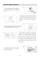
SAFETY PRECAUTIONS 4. To prevent damage to the equipment, please unplug from the power outlet if not in use. 5. To unplug the equipment, always handle the power cord using the plug. Do not unplug out the equipment by pulling the cord. 6. Place the equipment on a stable surface and avoid placing other objects on top of it. 7. Cleaning: Use a soft, dry cloth for cleaning. For stubborn dirt, soak the cloth in a weak detergent solution; wring well and wipe to remove the dirt.
FUNCTIONS 1. 2. 3. 4. 5. 6. Front panel MICROPHONE input: XLR + 1/4’’ jack combo (balanced and unbalanced). The microphone preamplifier with differential (balanced) input mode provides a clear signal and limits noise. TALK OVER switch Set this switch to “ON” to reduce the volume of channel 1, channel 2 and the USB device, so that the microphone signal stands out. Set this switch to the “OFF” position to switch off this Talk Over function. Gain adjustment This function adjusts the microphone signal.
FUNCTIONS 7. 8. 9. 10. 11. 12. 13. 14. 15. 16. 17. 18. 19. 20. 21. Front panel Left INSERT switch Hold down this button to force the channel 1 audio signal to be inserted into the general output, regardless of the position of the CROSSFADER control. CROSSFADER control switch This function decreases the signals of the right and left channels.
FUNCTIONS Front panel 22. Monitor potentiometer Allows you to adjust the volume of the monitoring channel. 23. VU METER Indicator with lit bars, for a precise visualisation of the output signals. 24. Power supply switch Controls the voltage power of the equipment. 25. Power supply indicator light This lights up when the unit is switched on. 26.
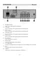
FUNCTIONS Rear panel 31. Headphones output Sends stereo output signal to headphones. 32. CD1 input Receives all kinds of CD signals (balanced and unbalanced). 33. LINE1 socket Receives all kinds of line signals (balanced and unbalanced). 34. CD2 input socket Receives all kinds of CD signals (balanced and unbalanced). 35. LINE2 socket Receives all kinds of line signals (balanced and unbalanced). 36. Record output Sends the signals to a recorder. 37. Mixing output Sends the mixed signal to main speakers.
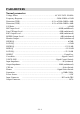
PARAMETERS Normal parameters Voltage Power …………………………………………..……AC 85V-265V 50/60Hz Frequency Response…………………………………….…………20Hz-20KHz ±0.5dB Distortion (THD)……...…….................................................0.1% at 20Hz-20KHz +4dB Distortion (THD)…………….….......................................... 0.1% at 20Hz-20KHz +4dB S/N Ratio…………………………………………………………………………≥80dB MIC Input Level ………………………………...………………-40dB (unbalanced) Line/CD Input Level......................................................................
PARAMETERS Input parameters Input terminal Input impedance Rated impedance Input level (dB) (Ω) (Ω) CD1 10K 100 0/10 LINE1 10K 100 0/10 CD2 56K 100 0/10 LINE2 10K 100 0/10 MIC 1K 100 -50 Output parameters Output terminal Output impedance Rated impedance Output level (Ω) (Ω) (dB) PHONES 100 600 >10mW (ST) REC 100 600 +4 MASTER (L/R) 100 600 +4 Connector polarity MIC INPUT HEADPHONES RECORD AND MIX Tip: hot Sleeve: ground Tip: hot (+) Ring: cold (-) Sleeve: gro
PARAMETERS Weight and dimensions MODEL WEIGHT Dimensions (W x D x H) DJX 480 PK 3,7kg 482 x 220 x 90 mm GB-10
APPLICATION GB-11
Disposal of waste electrical & electronic equipment (applicable in the European Union and other European countries with separate collection systems). This symbol on the product or on its packaging indicates that this product must not be treated as household waste. Instead it must be handed over to the applicable collection point for the recycling of electrical and electronic equipment.
DJX 480 PK / CDX-310 PROFESSIONAL DUAL CD PLAYER USER MANUAL www.my-scott.
PROFESSIONAL DJ DUAL CD PLAYER - USER MANUAL 1 2 3 4 5 6 7 8 9 10 23 11 1213 14 1516 18 20 22 24 17 19 21 ENGLISH CAUTION To prevent electric shock do not disassemble this unit. No user serviceable parts inside. Refer servicing to qualified servicing personnel. IMPORTANT Use of controls or adjustments or performance of procedures other than those specified in this manual may result in hazardous radiation exposure. Professional DJ dual CD player y 1 bit D/A converter with 8 times oversampling.
FRONT PANEL CONTROLLER: 1. SHUTTLE (SHUTTLE DIAL) Use this dial to select the scanning direction and speed. The disc is scanned forwards when the shuttle dial is turned clockwise from the neutral position, and backwards direction when the shuttle dial in turned counter clockwise. The scanning speed increases when the shuttle dial is turned faster. 2. OPEN/CLOSE (OPEN/CLOSE BUTTON) Press this button once to open or close the disc compartment. The main unit also includes OPEN/CLOSE buttons.
FRONT PANEL CONTROLLER: 13. CUE INDICATOR When in CUE mode, the CUE indicator lights up. 14. CUE (CUE BUTTON) Press the CUE button during playback to return to the position at which playback started. 15. +10 (TRACK +10 BUTTON) Use this button to skip ahead 10 tracks. 16. PLAY/PAUSE BUTTON Use this button to start playback. Press once to start playback, twice to set the pause mode, and three times to resume playback. 17. PLAY INDICATOR The PLAY indicator lights up during play mode. 18.
CONNECTIONS: 3 2 5 1 3 4 5 6 FUNCTIONS: Opening & closing the disc compartment. Turn the unit power on. Press the OPEN/CLOSE button to open the disc compartment. OPEN/CLOSE buttons are provided on both the main unit and control unit. You cannot open the disc compartment when the unit is reading a disc. Push the START / PAUSE button before pushing the OPEN / CLOSE button.
Starting playback Press the PLAY/PAUSE button during the pause or cue mode to start playback. The PLAY indicator lights up. The point at which playback starts is automatically stored in the memory as the cue point. The player then returns to the cue point when the CUE button is pressed. (Back Cue) Figure 4-1 Stopping Playback There are two ways to stop playback: Press the PLAY/PAUSE button during playback to pause at that point.
Cueing − "Cueing" is the action of preparing for playback. − Press the CUE button: the player will enter cue mode. It will return to the cue point and enter pause mode, while the cue indicator lights up and the play indicator flashes. When the PLAY/PAUSE button is pressed, play starts from the cue point. − When the track search operation is completed after pressing the SKIP ( / ) buttons, the player automatically finds the position at which the sound starts and places the cue point there (Auto Cue).
Matching the Beats Per Minute (BPM) for two CDs There are three tools available for matching the BPM of two CDs: − Use the pitch slider to adjust the BPM. − Use the PITCH BEND +/- buttons to change the BPM temporarily. − Turn the JOG dial to change the BPM temporarily. a. Pitch Slider 1. To adjust the BPM by sliding the pitch slider up or down, press the PITCH button to turn on the PITCH adjustment function before using. 2. Slide the pitch slider up to decrease the BPM, or down to increase the BPM.
INSTALLING THE UNIT: 1. Place your unit on a flat surface or mount it in a secure rack mount case. 2. Be sure the player is mounted in a well-ventilated area where it will not be exposed to direct sunlight, high temperatures, or high humidity 3. Try to place the unit as far as possible from TVs and tuners, as the unit may cause undesirable interference CAUTION The player will work normally when the main unit is mounted with the front panel at within 15° of the vertical plane.
DISPOSAL: Disposal of old electrical & electronic equipment (applicable in the European Union and other European countries with separate collection systems). This symbol on the product or on its packaging indicates that this product must not be treated as household waste. Instead it must be handed over to the relevant collection point for the recycling of electrical and electronic equipment.
DJX 480 PK / AX-121 PROFESSIONAL AMPLIFIER USER MANUAL
CONTENTS Features…………………………………………………….GB-1 Safety Instructions…………………………………………GB-2 Components and functions Front Panel …………………………………………………GB-4 Back Panel………………………………………………….GB-4 System Connections………………………………………..GB- 5 Operation…………………………………………………...GB-8 Troubleshooting……………………………………………GB-9 Technical Specifications…………………………………...
SAFETY PRECAUTIONS The lightning flash with an arrowhead symbol within an equilateral triangle is intended to alert the user to the presence of uninsulated dangerous voltage within the product’s enclosure that may be of sufficient magnitude to constitute a risk of electric shock to persons. The exclamation mark within an equilateral triangle is intended to alert the user to the presence of important operating and maintenance (servicing) instructions in the literature accompanying the appliance.
SAFETY PRECAUTIONS 3. Do not install the equipment in a dusty, damp or poorly ventilated place. 4. To prevent damage to the equipment, please unplug from the power outlet if not in use. 5. To unplug the equipment, always handle the power cord using the plug. Do not pull out the plug by tugging the cord. 6. Place the equipment on a stable surface and avoid placing other objects on top of it. 7. Cleaning care: Use a soft, dry cloth for cleaning.
COMPONENTS AND FUNCTIONS All the components are located on the front or back panel. FRONT PANEL 1. Power switch 2. Left channel volume adjust dial 3. Left channel overload indicator 4. Right channel volume adjust dial 5. Right channel overload indicator REAR PANEL 1. Right channel unbalanced signal input (INPUT RIGHT) 2. Left channel unbalanced signal input (INPUT LEFT) 3. Right channel speaker output 4. Left channel speaker output 5. AC power socket and fuse socket 6.
SYSTEM CONNECTIONS The circuitry in this amplifier has an unbalanced input. According to the diagram below, you can see that the amplifier can be connected to a balanced or unbalanced source. Each channel has an unbalanced input socket (6.3 mm), and the input must be connected to the ground. XLR signal output connector (balanced signals) 6.3mm three-wire earphones plug (balanced wire input) XLR output connector (balanced signals) 6.3mm two-wire earphones plug RCA output jack (unbalanced signal) 6.
SYSTEM CONNECTION A. Loosen one of the screws. B. Slide the protection sheet to one side. C. Select the required voltage using the switch. D. Slide the protection sheet back to its original position and tighten the screw. Note: Do not loosen the two screws at the same time. Read the previous sections on system connections. Check whether the local power voltage is consistent with the requirements of the unit and whether the unit is turned off before making the connections.
SYSTEM CONNECTION GB-7
OPERATION When switching the system on or off, we advise you to switch on the amplifier last and switch it off first so as to prevent any impact caused by the ON/OFF switch. Check whether the local power voltage the same as the one indicated on the back panel and that all the connections are correct before turning the power on. Turn the volume adjustment dials for the left and right channels anti-clockwise to the (-∝) position.
TROUBLESHOOTING Please refer to the table below in order to solve any problems when using the amplifier. If the problem persists, please contact a professional technician or contact our company. Never try to repair the appliance yourself. Problem No sound Possible reason(s) 1. The power plug is in the wrong position. 2. The speakers are not connected properly. 3. The inputs/outputs are not connected properly. 4. Short-circuit of the speaker terminal. 5. The volume buttons are adjusted to the minimum.
TECHNICAL SPECIFICATIONS Rated output for each channel 8 ohms @ 1kHz, 1% THD+N……………………………..128 watts RMS per channel 4 ohms @ 1kHz, 1% THD+N……………………………..225 watts RMS per channel S/N Ratio………………..>95dB, 22Hz-22kHz bandwidth referenced to rated output Frequency response………………………..…..………….10Hz-20kHz (+0, -0.5dB) Damping factor……………………………………………………………………200 Slew rate……………………………………………………….
Disposal of waste electrical & electronic equipment (applicable in the European Union and other European countries with separate collection systems). This symbol on the product or on its packaging indicates that this product must not be treated as household waste. Instead it must be handed over to the applicable collection point for the recycling of electrical and electronic equipment.
DJX 480 PK / S – 12 PROFESSIONAL SPEAKER USER MANUAL
Table Of Contents Important safety precautions....................................................... GB-2 Features…………………………………………………………..GB-2 Components………………………………………………………GB-3 Connecting The Speaker System………………………………..GB-4 Choosing a power amplifier to connect to the DJX 480 PK.......GB-5 Quick Set-Up………………………………………………….….GB-6 Installing the DJX 480 PK………………………………………GB-7 Technical specifications................................................................GB-8 .
Important Safety Precautions 1. 2. 3. 4. 5. 6. 7. Please read all instructions before operating the unit. Keep these instructions for future reference. Please pay attention to all safety warnings. Follow the manufacturer’s instructions. Do not use this unit near water or moisture. Clean only with a damp cloth. Do not install near any heat sources such as radiators, heat registers, stoves, or other apparatus (including amplifiers) that produce heat. 8.
Components FRONT PANEL ①HF Driver – the DJX 480 PK uses a piezo driver with a 1” throat. ②Low frequency - Custom designed, heavy-duty, 12" driver providing deep bass. ③Port Tube - Two precision tuned, low frequency port tubes extending the bass response. ④Handle - one handle on the top of the speaker. ⑤Grille - Durable steel grille to protect the driver. ⑥Wood casing with carpet finish. BACK PANEL INPUT/EXTENSION: 6.
Connecting The Speaker System Choosing the correct cables The speaker connections must be made using the 6.35 mm MIC connectors on the back panel. You can use a variety of standard speaker cables that are available at your local professional audio retailer or musical instrument retailer. Ensure that standard, stranded speaker wire cables are used. A diameter between 1.63 and 2.03 mm is recommended. If you are making your own cables, use the diagrams below to ensure proper connections.
Choosing an amplifier to connect to the DJX 480 PK The speaker has a specific power rating, which you can find out by checking the label at the back of the speaker. Refer to the Technical specifications section of this manual, to check that your power amplifier has the correct power output for this speaker. Be careful to consider the total impedance if you are connecting more than one speaker to one side of a stereo power amplifier.
Quick Set-Up Follow the diagram and steps below to set up a basic stereo PA system quickly. NOTE: Before plugging in and turning on the appliances, it is important to remember the rule: “LAST ON, FIRST OFF”. In other words, this means that when turning on your system, you should always turn your power amplifiers or powered monitors on LAST, and when turning your system off, turn your power amplifiers off FIRST.
Installation of the DJX 480 PK Microphone Positioning-How to Reduce Feedback Feedback is the annoying howling and squealing that is heard when the microphone is too close to the speaker and the volume is high. You get feedback when the microphone picks up the amplified signal from the speaker, and then amplifies through the speaker again, and then picks it up again, and so on and so on.
Technical specifications Max. Power………………300 Watts Nominal Impedance………8 Ohms Frequency Response……..50-20k Hz Sensitivity………………..95 dB LF Driver………………..12-inch heavy-duty driver HF Driver………………...Piezo driver Speaker Type…………….Bass Reflex Mounting………………...Internal 1.39 inch (35 mm) receptacle Net Weight………………11.8 Kg Disposal of waste electrical & electronic equipment (applicable in the European Union and other European countries with separate collection systems).