
Full Product Manual


• Replace the sprocket cover ensuring that the adjusting pin in
the chain cover is in the bar chain tensioning pin hole and
that both bar studs are securely in their respective holes in
the sprocket cover. (Fig. 10)
• Replace the sprocket cover and bar mounting nuts.
Finger-tighten the bar mounting nuts. The bar must be free
to move for tension adjustment. (Fig. 11)
• Remove all slack from the chain by turning the chain
tensioner clockwise until the chain seats snugly against the
bar with the drive links in the bar groove. (Fig. 12)
• Fully tighten the two bar mounting nuts.
The chain is correctly tensioned when there is no sag on the
underside of the guide bar, the chain is snug, but it can be
turned by hand without binding.
NOTE: If chain is too tight, it will not rotate. Turn the chain
tensioner 1/4 turn counterclockwise. Lift the tip of the guide bar
up and retighten the knob. Ensure that the chain will rotate
without binding.
NOTE: A new chain tends to stretch, check chain tension
frequently and tension as required.
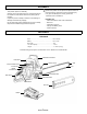
INSTALLING/REPLACING THE GUIDE BAR AND CHAIN
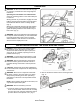
• Remove the old chain from the bar.
• Lay out the new saw chain in a loop and straighten any links.
The cutters should face in the direction of the chain rotation.
If they face backwards, turn the loop over. (Fig. 7)
• Place the chain drive links into the bar groove.
NOTE: Make certain of the direction of the chain.
• Position the chain so there is a loop at the back of the bar.
(Fig. 8)
• Hold the chain in position on the bar and place the loop
around the sprocket.
• Fit the bar flush against the mounting surface so that the bar
studs are in the long slot of the bar. (Fig. 9)
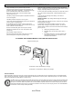
Fig. 7
Fig. 8
Fig. 10
Fig. 11
Fig. 12
Fig. 9
8
Model LCS31662S