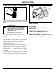
K9 Lawn Tractor S2546 OPERATOR’S MANUAL ÿþýþüûúùøúþüþ÷ö Manufactured by John Deere OMGX10722 K9 North American Litho in U.S.A.
INTRODUCTION Introduction THANK YOU for purchasing a Scotts product. B A Read this manual and your attachment manual thoroughly. Failure to do so could result in personal injury or equipment damage. c WARNING: The Engine Exhaust from this product contains chemicals known to the State of California to cause cancer, birth defects or other reproductive harm.
TABLE OF CONTENTS Table of Contents Contents Assembly ............................................................................................................................................... 1 Safety Signs........................................................................................................................................... 3 Controls .................................................................................................................................................
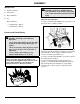
ASSEMBLY Assembly Identify Parts c CAUTION: Avoid injury. DO NOT attempt to A Operator’s Manual B Safety Video C Bag of Hardware D Key NOTE: Do not remove the BLACK negative (–) protective cap at this time. Bag of Hardware: 1. Remove and discard the RED positive (+) protective cap from the positive (+) battery terminal. • 2 - M8x16 Bolts - Battery • 2 - M8x16 Nuts - Battery open, add fluid or service battery. Any attempt to do so will void warranty and lead to possible injury.
ASSEMBLY Checking Tire Pressure c CAUTION: Avoid injury. Explosive separation of a tire and rim parts can cause serious injury or death: - Do not attempt to mount a tire without the proper equipment and experience to perform the job. - Always maintain the correct tire pressure. Do not inflate the tires above the recommended pressure. Never weld or heat a wheel and tire assembly. The heat can cause an increase in air pressure resulting in a tire explosion.
SAFETY SIGNS Safety Signs Safety-Alert Symbol • Do not mow in reverse • Look down and behind before and while backing • Never carry children WARNING AVOID SERIOUS INJURY OR DEATH • Drive up and down slopes, not across • Avoid sudden turns • If machine stops going uphill, stop blade and back down slowly Read and recognize safety information. Be alert to the potential for personal injury when you see this safety-alert symbol.
SAFETY SIGNS DANGER ROTATING BLADE DO NOT PUT HANDS OR FEET UNDER OR INTO MOWER WHEN ENGINE IS RUNNING M96445 Picture Note: Located on Battery under seat DANGER ROTATING BLADE M96445 DO NOT PUT HANDS OR FEET UNDER OR INTO MOWER WHEN ENGINE IS RUNNING Picture Note: Located on Left-Hand side of deck THROWN OBJECTS BEFORE MOWING, CLEAR AREA OF OBJECTS THAT MAY BE THROWN BY BLADE DO NOT OPERATE MOWER WITHOUT DISCHARGE CHUTE OR ENTIRE GRASS CATCHER IN PLACE M96445 Picture Note: Located on Right-Hand side
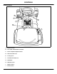
CONTROLS Controls Tractor Controls J I A B H C G D F E A - Throttle Control B - Foot Pedal - Brake/Return to Neutral C - Reverse Implement Option Switch D - Attachment Lift Lever E - Locking Lever F - Transmission Shift Lever G - Park Brake H - PTO Drive Lever I - Ignition Switch J - Choke Control Controls - Page 5
OPERATING MACHINE Rotating Blades are Dangerous - Protect Children and Prevent Accidents Operating Machine Operate Safely PROTECT CHILDREN: • In addition to reading your Operator’s Manual, view your Mowing Safety Video. • Check brake action before you operate. Adjust or service brakes as necessary. • Inspect machine before you operate. Be sure hardware is tight. Repair or replace damaged, badly worn, or missing parts. Be sure guards and shields are in good condition and fastened in place.
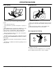
OPERATING MACHINE Avoid Tipping Keep Riders Off • • Only allow the operator on the machine. Keep riders off even if blades are shut off. DO NOT drive where machine could slip or tip. • Stay alert for holes and other hidden hazards in the terrain. • Keep away from drop-offs. • Slow down before you make a sharp turn or operate on a slope.
OPERATING MACHINE Transport Safely Using the Park Brake c CAUTION: Avoid injury. Always LOCK park brake before getting off tractor or leaving tractor unattended. LOCKING PARK BRAKE: A • Use safety lights and devices. Slow moving machines when driven on public roads are hard to see, especially at night. Avoid personal injury or death resulting from a collision with a vehicle. B • Whenever driving on public roads, use flashing warning lights and turn signals according to local regulations.
OPERATING MACHINE UNLOCKING PARK BRAKE 1. Push and hold foot pedal (A) all the way down. 2. Move park brake lever (B) to the right, then to the rear. 3. Remove foot from pedal. Pedal should return to the up position. Starting Engine 4. Push throttle lever (D) up to the FAST ( r) position and pull out choke knob (E). As the engine begins to run smoothly, push the choke knob in until it is fully seated. 5. Turn ignition key (F) to start position to crank the engine.
OPERATING MACHINE 4. Move throttle lever (D) to SLOW (t) position. Let engine run at low throttle a few seconds. Warming and Idling Engine WARMING ENGINE: • 5. Turn key (E) to OFF position. Run Engine at half speed for 2–3 minutes. 6. Remove key. IDLING ENGINE: 7. LOCK the park brake. A Using Travel Controls c CAUTION: Avoid injury: M96455 • Engine is air-cooled and needs a large volume of air to keep cool. Keep air intake screen (A) on top of engine clean.
OPERATING MACHINE TO TRAVEL IN REVERSE: NOTE: The engine and mower will stop as the shift lever is moved to the R (REVERSE) position with mower engaged. 1. Pull PTO lever (C) all the way back to the rearward (OFF) position. 2. Look behind the vehicle to be sure there are no bystanders nearby. A 3. Move shift lever (A) rearward to the R (REVERSE) position. FOR EMERGENCY STOPPING: 1. Push foot pedal (B) fully to stop machine. Transmission shift lever (A) will automatically return to NEUTRAL.
OPERATING MACHINE Pushing Machine Testing Safety Systems IMPORTANT: Avoid transmission damage, DO NOT tow machine. c CAUTION: Avoid injury. Engine exhaust fumes can cause sickness or death. To move machine when engine is STOPPED: If it is necessary to run an engine in an enclosed area, remove the exhaust fumes from the area with an exhaust pipe extension. If you do not have an exhaust pipe extension, open the doors and get outside air into the area.
OPERATING MACHINE Test 2 Test 4 1. Operator on seat. 1. Operator on seat. 2. Lock the park brake. 2. Push brake pedal down. A A C 3. Push PTO lever (A) forward to ENGAGE. B 4. Try to start engine. 5. Engine MUST NOT start. If engine starts, there is a problem with your safety interlock circuit. (See your Authorized Service Center.) Test 3 1. Operator on seat. 3. Pull PTO lever (A) back to DISENGAGE. 2. Lock the park brake. 4. Put transmission shift lever (B) in N (NEUTRAL) position. 5.
OPERATING MACHINE Test 7 A B c CAUTION: Avoid injury. Before moving rearward, make sure area is clear of bystanders, especially children. Test Reverse Implement Option: 1. Start engine. 3. Pull PTO lever (A) back to DISENGAGE. 4. Start engine and move throttle lever (B) to FAST (r) speed position. A 5. Raise up off of seat. DO NOT get off tractor. 6. Engine MUST remain running. If engine does stop, there is a problem with your safety interlock circuit. (See your Authorized Service Center.) 2.
OPERATING MACHINE Avoid Using Ground Engaging Equipment Transporting Do not tow machine. IMPORTANT: Avoid machine damage. This tractor is NOT intended for use with ground engaging equipment. Use of such equipment could result in damage to transmission components. Use a heavy-duty trailer to transport your machine. Raise mower deck to highest position when transporting to trailer. Disengage PTO.
OPERATING MOWER • DISENGAGE PTO lever to stop mower blades when you are not using mower. Operating Mower Operate Mower Safely • In addition to reading your Operator’s Manual, view your Mowing Safety Video. Using Lift Lever to Raise and Lower Mower Check Ground Conditions A B • Clear mowing area of objects that might be thrown. Keep people and pets out of mowing area. • Study mowing area. Set up safe mowing pattern. Do not mow under conditions where traction or stability is doubtful.
OPERATING MOWER Adjusting Mower Gage Wheels Adjusting Mower Level (Side-to-Side) c CAUTION: Avoid injury, before you adjust gage wheels: STOP engine, remove key, and wait for blades to STOP. IMPORTANT: Avoid machine damage. Mower gage wheels must not ride on ground to support mower weight. Adjust gage wheels each time you change cutting height. 1. Check tractor tire pressure. Inflate tires to the correct pressure. (See Checking Tire Pressure in Service Miscellaneous section.) 2.
OPERATING MOWER A C B D E 7. Loosen top clamping nut (C) facing inside of mower, on left hand side J-bolt (B), approximately one turn. 8. Loosen upper adjusting nut (D). 9. Raise or lower left side of deck. 4. Turn blades so front blade tips (A) point straight forward. 5. Measure from the front of each blade tip to the level surface. The front blade tips must be 6–9 mm (1/4–3/8 in.) lower than rear blade tips or blades will cut grass twice and grass tips will turn brown.
OPERATING MOWER Engaging and Disengaging Mower Dismounting to Inspect or Unplug Mower or Optional Bagger IMPORTANT: Avoid machine damage. Operate engine at maximum speed when mowing or after mower blade is engaged. Machine may require 2–3 minutes warm-up period before engaging the mower deck. Engaging Mower c CAUTION: Avoid injury. To help prevent personal injury, do the following steps before you dismount to inspect or unplug mower or bagger. 1. STOP machine. 1. START engine. A A B 2.
REPLACEMENT PARTS Replacement Parts John Deere Quality WE RECOMMEND JOHN DEERE quality parts and lubricants, available at your Authorized Service Center. PART NUMBERS MAY CHANGE, use part numbers listed below when you order. If a number changes, your dealer will have the latest number. WHEN YOU ORDER PARTS, your Authorized Service Center needs your machine serial number and engine serial number. These are the numbers that you have recorded on the inside front cover of this manual.
SERVICE MACHINE SAFELY wear a suitable protective device such as earplugs. Service Machine Safely Practice Safe Maintenance • Do not wear radio or music headphones while servicing the machine. Safe service requires your full attention. Avoid Injury From Contacting Blades • Understand service procedure before doing work. Keep area clean and dry. • Never lubricate, service, or adjust machine while it is moving. Keep safety devices in place and in working condition. Keep hardware tight.
SERVICE INTERVAL CHART Service Interval Char t Service Intervals Please use the following timetables to perform routine maintenance on your machine. Service procedures included in this manual but not on this chart are to be performed on an as needed basis. IMPORTANT: Avoid machine damage. If you operate mower in extreme heat, dust or other severe conditions, service more often than shown below. Before Each Use Test safety systems. Check brakes. Check tire pressure. Check/tighten loose hardware.
SERVICE INTERVAL CHART Service Record DATE SERVICE PERFORMED Service Interval Chart - Page 23
SERVICE ENGINE Service Engine Adjusting Carburetor NOTE: Carburetor is calibrated by the engine manufacturer and should not require any adjustments. If engine is operated at altitudes above 1829 m (6,000 ft.), some carburetors may require a special high altitude main jet. See your John Deere dealer. engines. The use of multi-viscosity oil such as (10W30) in ambient temperatures above 4° C (40° F) will result in higher than normal oil consumption.
SERVICE ENGINE Checking Engine Oil Changing Engine Oil and Filter IMPORTANT: Avoid machine damage. To avoid engine damage, DO NOT run engine if oil level is below ADD mark. NOTE: Engine must not be running. Make sure engine is COLD when checking engine oil level. c CAUTION: Avoid injury. Engine may be hot, be careful not to burn hands. IMPORTANT: Avoid machine damage.
SERVICE ENGINE Checking and Cleaning Air Cleaner Elements IMPORTANT: Avoid machine damage. To extend engine life, when operating mower in extreme heat, dust or other severe conditions, it may be necessary to check/replace air cleaner more frequently. C 1. Lift hood. MX1529 7. Remove old filter (C) and wipe off filter tray with a clean cloth. 2. Clean any dirt and debris from the air cleaner before removing cover. 3. Loosen knob (A) and remove cover (B). A 8.
SERVICE ENGINE if necessary. IMPORTANT: Avoid machine damage. To prevent engine damage, DO NOT allow any foreign objects to fall into the carburetor air intake (C). 8. Carefully clean air cleaner housing. Prevent any dirt from falling into carburetor. 9. Install foam precleaner (E) mesh side up. 10.Install cartridge. Make sure cartridge and seal are properly seated and sealing the carburetor air intake area. 11.Install air cleaner cover and tighten knobs. DO NOT overtighten. 12.Lower hood.
SERVICE ENGINE Replacing Fuel Filter A c CAUTION: Avoid injury. Keep cigarettes, sparks, and flames away from the fuel system. Make sure engine is cool to the touch. IMPORTANT: Avoid machine damage. When disconnecting fuel tank hose from filter, be sure to hold hose above fuel tank level so fuel does not run out. A NOTE: 2. Disconnect spark plug wires (A) and remove spark plugs. 3. Clean spark plugs carefully with a wire brush. 4. Inspect plug for: • Cracked porcelain. • Pitted or damaged electrodes.
SERVICE STEERING AND BRAKES Lubricating Front Wheel Spindles, Wheel Bearings and Axle Pivot Service Steering and Brakes Grease 50°C 122°F 86°F 20°C 68°F 10°C 50°F 0°C 32°F - 10°C 14°F - 20°C - 4°F - 30°C - 22°F - 40°C - 40°F - 55°C - 67°F NGLI Number 30°C NGLI Number 104°F NGLI Number 40°C C Park tractor on flat, level surface. STOP engine, LOCK park brake, DISENGAGE PTO lever, turn key to the OFF position, and remove key.
SERVICE STEERING AND BRAKES Adjusting Brakes spring bracket and front edge of brake rod stop tabs. Gap should have a minimum distance of 2 mm (0.08 in). c CAUTION: Avoid injury. Before adjusting • Check brake rod compression spring (E). It should not be completely compressed when park brake is locked. A slight air gap should be visible between the coils when proper adjustment is reached. brakes: STOP engine. Remove key. Wait for all moving parts to STOP.
SERVICE MOWER 20°C 68°F 10°C 50°F 0°C 32°F - 10°C 14°F adjust or service mower: - 20°C - 4°F - DISENGAGE PTO switch to stop mower blades. - 30°C - 22°F - 40°C - 40°F - 55°C - 67°F c CAUTION: Avoid injury. Before you unplug, - Wait for mower blades to STOP. NGLI Number 86°F NGLI Number 30°C BIO-GREASE- 104°F GREASE- 40°C JD High Temp 122°F JD Moly High Temp 50°C Arctic Avoid Injury From Contacting Blades NGLI Number Grease Service Mower - LOCK the park brake.
SERVICE MOWER Replacing Mower Drive Belt A B C F c CAUTION: Avoid injury. Before replacing mower drive belt: STOP engine, remove key, wait for all moving parts to STOP, and wear gloves when replacing belt. E 1. STOP engine, LOCK park brake, place gear shift lever in NEUTRAL (N) position, pull PTO drive lever back to DISENGAGE, turn key to the OFF position, and remove key. C D F 2. Remove mower deck. (See Removing Mower in Removing Mower section.) 3.
SERVICE MOWER Adjusting Spindle Brake c CAUTION: Avoid injury from rotating blades. Mower blades must stop within 5 seconds after mower is turned off. Check spindle brake measurement every 25 hours or once a year (whichever comes first). IMPORTANT: damage. 7. Measure distance from brake surface (A) to pulley braking surface (B). Brake to Pulley Distance should be: 2 – 3 mm (0.08 – 0.12 in). 8.
SERVICE MOWER Checking Mower Blades c CAUTION: Avoid injury. Before adjusting D Mower Belt Tension: STOP engine. Remove key. Wait for all moving parts to STOP. C B To check for a bent blade: A M88119b 3. Loosen and remove cap screw (A), hardened washer (B), cupped blade washer (C) and blade (D). 4. Inspect blades; sharpen/balance or replace as necessary. INSTALLING MOWER BLADES 1. Lower mower. Measure distance between blade tip and flat ground surface. 1.
SERVICE MOWER Sharpening Blades c CAUTION: Avoid injury. Wear goggles and gloves when you handle blades. 1. Sharpen blades with grinder, hand file or electric blade sharpener. A B 2. Keep original bevel (A) when you grind. 3. Blade should have 0.40 mm (1/64 in.) cutting edge (B). Balancing Blades c CAUTION: Avoid injury. Wear goggles and gloves when you handle blades. 1. Clean blade. 2. Put blade on nail in vise or on vertical wall stud. Turn blade to horizontal position. 3.
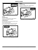
SERVICE ELECTRICAL Service Electrical Checking the Battery B c CAUTION: Avoid injury. Sulfuric acid in battery C electrolyte is poisonous. It is strong enough to burn skin, eat holes in clothing, and cause blindness if splashed into eyes. Wear eye protection and avoid spilling or dripping electrolyte. A Flush eyes with water for 15-30 minutes if acid is splashed into eyes. If acid is swallowed, get medical attention immediately. DO NOT attempt to open, add fluid or service battery.
SERVICE ELECTRICAL c CAUTION: Avoid injury. BE VERY CAREFUL: B Battery fluid (electrolyte), is a solution of water and sulfuric acid. It is very harmful to eyes, skin, or clothing. C - Wear goggles or an eye shield when you work with a battery. A - If the acid contacts your eyes, skin, or clothing, flush the area immediately with water. Get medical help, if necessary. M96453 3. Disconnect BLACK (–) battery cable (B) first. A battery gives off gas which can explode.
SERVICE ELECTRICAL TO ENGINE GROUND B A VEHICLE BATTERY 2. Connect positive (+) charger cable to positive (+) battery terminal. 3. Connect negative (–) charger cable to negative (–) battery terminal. C D BOOSTER BATTERY 2. Connect the other end of positive (+) booster cable to vehicle battery positive (+) post (A). 3. Connect negative (–) booster cable to booster battery negative (–) post (C). 4. Connect the other end of negative (–) booster cable (B) to engine ground away from battery. 4.
SERVICE ELECTRICAL Replacing Fuse 1. Open hood. A MX1535 2. Pull defective fuse (A) out of socket. 3. Check metal clip in fuse window and discard fuse if clip is broken. 4. Push new fuse into socket. 5. Close hood.
SERVICE MISCELLANEOUS Fuel Service Miscellaneous Checking Tire Pressure c CAUTION: Avoid injury. Explosive separation of a tire and rim parts can cause serious injury or death: - Do not attempt to mount a tire without the proper equipment and experience to perform the job. - Always maintain the correct tire pressure. Do not inflate the tires above the recommended pressure. Never weld or heat a wheel and tire assembly. The heat can cause an increase in air pressure resulting in a tire explosion.
SERVICE MISCELLANEOUS varnish deposits, especially if fuel is stored for several weeks or more. Using clean, fresh fuel will help to prevent damage to the fuel system and will help maintain peak engine performance. If engine performance problems occur, use fuel from another supplier before suspecting machine problems. Suppliers blend fuels differently and changing suppliers will generally solve any performance problems.
SERVICE MISCELLANEOUS Avoid Damage: • “Dry wiping” or wiping the plastic surface when it is dry is a major source of minor surface scratches. • DO NOT wipe hood or other plastic parts unless wetted first. A • DO NOT apply wax unless plastic surface has been thoroughly cleaned first. • DO NOT use abrasive materials, such as polishing compounds, to clean or to wax plastic surface. M96452 4. Remove fuel tank cap (A). 5. Fill tank with fresh fuel only to bottom of filler neck. 6.
SERVICE MISCELLANEOUS 2. Use paint stick with factory-matched colors available from your John Deere dealer to fill scratches. Follow directions for use and for drying. • Apply sparingly to scratch without getting on surrounding painted surface. Fill in scratch to level of surrounding painted area. • Allow to dry 48 hours in warm weather and up to 30 days in colder temperatures. 3. Use automotive polishing compound to smooth out surface. Do not use power buffer. 4. Apply wax to surface.
REMOVING MOWER Removing Mower Removing Mower c CAUTION: Avoid injury. Before removing mower on machine: STOP engine. Remove key. Wait for all moving parts to STOP. • Mower lift lever under tension. To avoid injury, grasp lift lever securely and release lock slowly. 1. STOP engine, LOCK park brake, DISENGAGE PTO lever, turn key to the OFF position, and remove key. E D E D 2. Raise mower lift lever to highest position. 3. Put wood blocks under each side of mower. 4.
INSTALLING MOWER Installing Mower Installing Mower H c CAUTION: Avoid injury. Before installing mower on machine: STOP engine. Remove key. Wait for all moving parts to STOP. J H • Mower blades are sharp. To avoid injury, always wear gloves when handling mower deck. G J I • Mower lift lever under tension. To avoid injury, grasp lift lever securely and release lock slowly. 1. STOP engine, LOCK park brake, DISENGAGE PTO lever, turn key to the OFF position, and remove key. 2.
INSTALLING MOWER N O 12.Raise tension rod (N) and attach to blade drive arm (O) using flat washer (P) and spring locking pin (Q). Q P O N 13.Raise deck by pressing the lift lever lock and pulling the mower deck lift lever to its highest point. 14.Remove wood blocks from under deck. 15.Check for proper routing and position of all belts. 16.Level mower. (See Adjusting Mower Level (Side-to-Side and Front-to-Rear) in the Operating Mower section.) 17.Adjust gage wheels.
TROUBLESHOOTING Troubleshooting Using Troubleshooting Chart If you are experiencing a problem that is not listed in this chart, see your Authorized Service Center for service. When you have checked all the possible causes listed and you are still experiencing the problem, see your Authorized Service Center. Engine IF CHECK Engine will not start Out of fuel. Loose or corroded electrical connections. PTO drive lever is in ON position. Fuse is blown. Spark plug wire is loose or disconnected.
TROUBLESHOOTING IF CHECK Loss of power Cutting too much grass /too fast. Throttle in “CHOKE” position. Buildup of grass, leaves and trash under mower. Dirty air filter. Low oil/dirty oil. Faulty spark plug. Dirty fuel filter. Stale or dirty fuel. Water in fuel. Spark plug wire loose. Dirty engine air screen/fins. Dirty/clogged muffler. Loose or damaged wiring. Carburetor out of adjustment. Engine continues to run when operator leaves seat Faulty operator-presence safety switch.
TROUBLESHOOTING IF CHECK Engine Stops When Shift Lever Is Moved To The R (REVERSE) Position and Attachment Is Engaged Normal condition. (See Using Reverse Implement Option in the OPERATING section.) Mower IF CHECK Discharge Chute Plugging Belt worn or installed incorrectly. Grass too wet. Buildup of grass, leaves and trash under mower. Worn, bent or loose blade. Mower deck not level. Engine rpm too low. Travel speed too fast. Low/uneven tire pressure. Blades improperly installed.
TROUBLESHOOTING IF CHECK Grass Tips Are Jagged And Turn Grayish Brown After Mowing Dull mower blades. Bent blades. Front-to-rear blade adjustment not set properly. Mower Stops When Shift Lever Is Moved To The R (REVERSE) Position and Mower Is Engaged. Normal condition. (See Using Reverse Implement Option in the OPERATING section.
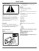
STORING MACHINE Preparing Engine For Storage Storing Machine Storing Safely NOTE: Properly preparing your tractor engine for storage will make it easier to start the following season. Engine storage procedure should be used if vehicle is not used for longer than 60 days. There are two satisfactory methods of preparing the engine for storage: running the engine completely dry of fuel, or filling the fuel tank with a mixture of fresh fuel and fuel stabilizer.
STORING MACHINE 7. Clean the engine and engine compartment. 8. Remove battery. 9. Clean the battery and battery posts. NOTE: The stored battery should be recharged every 90 days. 10.Charge the battery. (See Charging Battery in the SERVICE - ELECTRICAL section.) 11.Store the battery in a cool, dry place where it will not freeze. 12.Store the vehicle in a dry, protected place. If vehicle is stored outside, put a waterproof cover over it. Removing Machine From Storage 1. Check tire pressure.
SPECIFICATIONS Specifications Engine Engine Manufacturer . . . . . . . . . . . . . . . . . . . . . . . . . . . . . . . . . . . . . . . . . . . . . . . . . . . . . . . . . . . . . . . .Briggs & Stratton Horsepower (SAE1349) . . . . . . . . . . . . . . . . . . . . . . . . . . . . . . . . . . . . . . . . . . . . . . . . . . . . . . . . . . . . . . . 18.6 kW (25 hp) Displacement . . . . . . . . . . . . . . . . . . . . . . . . . . . . . . . . . . . . . . . . . . . . . . . . . . . . . . . . . . . . . . . . . . .
SPECIFICATIONS Tires Size (Front) . . . . . . . . . . . . . . . . . . . . . . . . . . . . . . . . . . . . . . . . . . . . . . . . . . . . . . . . . . . . . . . . . . . . . . . . . . . . 15 x 6.50 - 6 Size (Rear) . . . . . . . . . . . . . . . . . . . . . . . . . . . . . . . . . . . . . . . . . . . . . . . . . . . . . . . . . . . . . . . . . . . . . . . . . . . . . 20 x 10.0 - 8 Size (Rear) . . . . . . . . . . . . . . . . . . . . . . . . . . . . . . . . . . . . . . . . . . . . . . . . . . . . . . . . . . . .
WARRANTY Warranty LIMITED WARRANTY FOR NEW SCOTTS BRAND PRODUCTS Manufactured by John Deere (U.S. Only) A. GENERAL PROVISIONS - The warranties described below are provided by John Deere Company (“John Deere”) to the original purchasers of new Scotts Brand Products Manufactured by John Deere. Under these warranties, John Deere will repair or replace, at its option, any covered part which is found to be defective in material or workmanship during the applicable warranty term.
WARRANTY AND COVERED BY THIS WARRANTY OTHER THAN THOSE LISTED ABOVE. THIS EXCLUSION INCLUDES FUNDAMENTAL TERMS, REPRESENTATIONS, CONDITIONS AND WARRANTIES WHICH MAY BE EXPRESSED OR IMPLIED, VERBAL OR OTHERWISE, INCLUDING IMPLIED OR STATUTORY CONDITIONS OR WARRANTIES OF MERCHANTABILITY AND FITNESS, WHETHER PURSUANT TO THE SALE OF GOODS ACT OR ANY OTHER STATUTE OF ANY PROVINCE OR OTHERWISE, EXCEPT WHERE SUCH IMPLIED OR STATUTORY CONDITIONS OR WARRANTIES MAY NOT BE EXCLUDED BY LAW. F.
WARRANTY WARRANTED PARTS Coverage under this warranty extends only to the parts listed below (the emission control system parts) to the extent these parts were present on the engine purchased. Fuel Metering System: Fuel Metering System: Carburetor and internal parts (or fuel injection system). Cold start enrichment system. Air Induction System: to the first scheduled replacement for that part.
WARRANTY Limited Battery Warranty NOTE: Applicable in North America only. TO SECURE WARRANTY SERVICE The purchaser must request warranty service from a John Deere dealer authorized to sell John Deere batteries, and present the battery to the dealer with the top cover plate codes intact. FREE REPLACEMENT Any new battery which becomes unserviceable (not merely discharged) due to defects in material or workmanship within 90 days of purchase will be replaced free of charge.
INDEX A Air Cleaner Elements ............................................26 Air Intake Screen, Cleaning ..................................27 B Battery and Terminals, Cleaning ..........................36 Battery, Charging the ............................................37 Battery, Checking the ...........................................36 Battery, Removing and Installing .........................36 Battery, Using Booster ..........................................38 Belt Tension, Adjusting Mower ............
INDEX R Removing Mower .................................................44 Reverse Implement Option, Using ........................11 S Safety Labels ...........................................................3 Safety Systems, Testing ........................................12 Safety, Operating ....................................................6 Safety, Operating Mower ......................................16 Safety, Service ......................................................21 Safety, Service Mower ..
SERVICE LITERATURE Order Form John Deere Distribution Center - Department S/P P.O. Box 186, Moline, IL 61266-0186 To order these publications, call 1-800-522-7448. If you want manuals or catalogs for equipment not shown on this list, provide the model number, serial number, and name of the product when you call. Make checks payable to John Deere.
NOTES Notes Notes - Page 62
NOTES Notes - Page 63
INVESTMENT IN QUALITY Please do not return this tractor to the store where you purchased it. Your Scotts tractor, designed and built by John Deere, is more than just a purchase, it’s an investment in quality. That quality goes beyond our equipment to your dealer’s parts and service support. That’s why John Deere has initiated a process to handle your questions or problems, should they arise. If you have questions or problems with your new tractor, please follow the steps below.