
User's Manual


Screen Service SDT 200UB – SDT 500UB ARK-1 ATSC Operations
July, 2009 v 1.0 Page 3 - 5
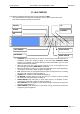
3.1.4 EQUIPMENT MOUNTING
Install the transmitter in an EIA (Standard 310) 19 inch rack as follows:
Place the equipment into the rack (2 units), align the mounting holes, and secure in place with four rack
screws.
If configured to operate, make sure the "LINE" switch on the front panel of the POWER SUPPLY &
METERING module is OFF.
Connect the power cord to an operating power source.
Note: We warmly suggest the installation of spike suppressors, line conditioners, isolation
transformers or other devices useful to protect the equipment.
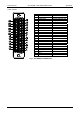
Connect the transmitting antenna cable to the "RF OUTPUT" connector in the rear panel.
Connect the Transport Stream source/s, SAT RECEIVER , GPS, SNMP PORT, AUX REMOTE and
CVBS/R,G,B to the relevant connectors on the front and rear panel.
REMEMBER TO CONNECT the equipment to the GROUND using the relevant screw located on the
rear panel.