
User's Manual


Screen Service SDT 200UB – SDT 500UB ARK-1 ATSC Operations
July, 2009 v 1.0 Page 3 - 14
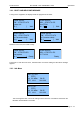
Reset system Enter this submenu to reset the device.
Change mode
Enter this submenu to change operating
mode (A or B).
Time and Date
Enter this submenu to change Time and
Date
3.2.5 LCD alarms
Through the LCD Alarms mask it is possible to select which alarm has to be notified on LCD
display. The alarm button is lighted and when an alarm condition occurs, alarms status is
displayed in the Alarms submenu.
The following table lists the alarms messages displayed on LCD, associated to the
corresponding alarm (refer to Alarms
paragraph for further information about alarms and
their masks).
Table 2.
Alarms descriptions list
Alarm Alarm Message
Up converter Osc. Unlock UPCV not locked
PS Voltage out of range PS V out of range
PS Current out of range PS I out of range
Absolute Power Limiter Abs. pwr high
Communication error UPCV dialog error
Temperature High Alarm Temperature high
Temperature Level-3dB Temp alarm (-3dB)
Temperature High Warning Temp warning
Forward Power High FWD power high
Forward Power Low Warning FWD low warning
Forward Power Low Alarm FWD low alarm
Reflex Power High RFL power high
Fan Speed Fans warning
S/N level RF in S/N low
GPS Lock GPS not locked
GPS Communication Error GPS dialog error
Signal 10 MHz Lock 10MHz not detected
Signal 129 MHz Lock 129MHz not detected
Signal 960 MHz Lock 960MHz not detected
Down Converter Osc. Unlock DWCV not locked
No RF Input In. not detected
RF Input Squelch RF in Squelch
RF Digital Ber Alarm RF BER high
File System Error FS wrong