
User's Manual


Screen Service SDT 200UB – SDT 500UB ARK-1 ATSC Operations
July, 2009 v 1.0 Page 3 - 34
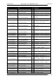
Table 4.
Bit-to-alarm association map
Alarm Bit Alarm Bit
Up converter Osc. Unlock 0 Signal 10 MHz Lock 16
PS Voltage out range 1 Signal 129 MHz Lock 17
PS Current out of range 2 Signal 960 MHz Lock 18
Absolute Power Limiter 3 Down Converter Osc. Unlock 19
Up converter communication error 4 No RF Input 20
Temperature High Alarm 5 RF Input Squelch 21
Temperature Level-3dB 6 RF Digital Ber. Alarm 22
Temperature High Warning 7 File System Error 23
Forward Power High 8 Bad File in File system 24
Forward Power Low Warning 9 No TS input 25
Forward Power Low Alarm 10 FPGA Boot alarm 26
Reflex Power High 11 Warm Up 27
Fan Speed 12 Not used
28
S/N Level 13 Not used
29
GPS Lock 14 Not used
30
GPS Communication Error 15 Not used
31
E.g. if you want to enable the GPS Lock and No TS Input alarms of a generic alarm mask,
set the decimal value of 33,570,816 that corresponds to a binary value of
0000 0010 0000 0000 0100 0000 0000 0000.
3.3.6 Traps
While a management station can poll, at fixed time interval, all the agents it knows for some
key information, each agent is responsible for notifying the management station of any alarm
condition. These events are communicated in SNMP messages known as traps.
The following parameters should be set in order to correctly configure traps:
• SNMP Agent Port: 162.
• SNMP Agent Transport protocol: IP/UDP.
• Variable
o OID: 1.3.6.1.4.1.21678.186.13.
o Value(gauge): 32 Bit
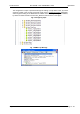
3.3.7 Configuring traps
Use Java (refer to Network and Alarms paragraphs for further information) or SNMP user
interfaces to configure traps.