
User's Manual


Screen Service SDT 200UB – SDT 500UB ARK-1 ATSC Operations
July, 2009 v 1.0 Page 3 - 68
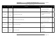
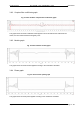
3.8.2 Complex filter coefficients graph
Fig. 21: Filter window: complex filter coefficients graph
This graph shows the actual coefficients values applied. The circles indicate the coefficients real
values, the red crosses indicate the imaginary ones.
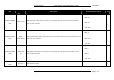
3.8.3 Module graph
Fig. 22: Filter window: module graph
This graph shows the actual module applied according to the coefficients calculated.
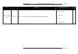
3.8.4 Phase graph
Fig. 23: Filter window: phase graph
This graph shows the actual phase applied according to the coefficients calculated.