
User's Manual


ISO 9001:2000 Cert. N°4500/1
Version 1.1 SDT_ARK6_User_Manual_ENG_vATSC Page 53 of 206
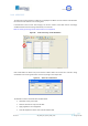
5.6.4.1 ATSC Measure window: RF power level monitor
Figure 21. ATSC Measure: RF power level monitor
Table 11. ATSC Measure: RF power level monitor
Box
Parameter / Control
Description
Admitted Ranges / Values
General
Monitor Tx Level
[dBm] /
Progress Bar
This value is the level of the signal, passing through the
transmission section and re-entering the system after the channel
filter, that will be used for the adaptive compensation.
The tolerance of the read value is ±1 dB.
Min: - 20
Max: 11,5
Low Power
High Power
General
Low Power Tx Signal
This alarm is raised when Max ADC Value is beneath the Low AGC
Threshold and, consequently, input attenuation is at its minimum
level.
Red: Alarm On
Grey: Alarm Off
General
High Power Tx Signal
This alarm is raised when Max ADC Value is beyond the High AGC
Threshold and, consequently, input attenuation is at its maximum
level.
Red: Alarm On
Grey: Alarm Off