Deutsch English Français Operating Manual Smart PRO Smart COM ® SWISS MADE BY UWATEC AG
Safety considerations You must carefully read and understand this entire manual before using your new computer. WARNING Diving has many inherent risks. Even if you follow the instructions of this manual in a careful manner, it is still possible that you may be seriously injured or die from decompression sickness, oxygen toxicity or some other inherent risk of scuba with Nitrox or compressed air.
I Safety considerations Avoid repeated ascents and descents (yo yo diving). Avoid repeated heavy workload while at depth. Plan the dives to be shorter if they are made in cold water. After finishing the decompression or at the end of a no-stop dive, the final stage of the ascent should be as slow as possible.
Introduction Congratulations on purchasing a Smart PRO or Smart COM dive computer and welcome to UWATEC. From now on you will enjoy the assistance of the most extraordinary dive computer - equipped with UWATEC's most innovative technology - while diving. This operating manual provides full information on the operation and functions of UWATEC Smart PRO and Smart COM dive computers.
Quick reference I Microbubble level icon (input / MB level reduced) Ready for input (O2 mix, MB level) Service icon O2 mix / Microbubble level / Battery capacity % F C Temperature Do not dive icon / Microbubble warning DEPTH Do not fly icon Dive time / No-fly time DIVE TIME NO Current depth NO h CNS O2% Ascent obligation Altitude sections Too fast ascent Total ascent time / Dive number SPEED Ascent time icon Desaturation time indicator DESAT ft h m DECO STOP LEVELSTOP NO STOP Maximum dept
List of chapters I Safety considerations Introduction Important remarks concerning signal words and symbols Quick reference / Operating scheme List of chapters ___________________________________ 2 ___________________________________ 4 ___________________________________ 4 ___________________________________ 5 ___________________________________ 6 II 1 System and operation System description ___________________________________ 8 ___________________________________ 8 2 Operation 2.
I 5 Functions at the Surface 5.1 End of a dive 5.2 Desaturation time 5.3 No-fly time 5.4 Microbubble warning __________________________________ 20 __________________________________ 20 __________________________________ 20 __________________________________ 20 __________________________________ 20 6 Diving in mountain lakes 6.1 Altitude ranges 6.2 Prohibited altitude 6.
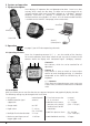
II System and operation 1 System description Smart displays all important dive and decompression data. Smart has a data memory which stores the dive data. The data can be transmitted with an infrared interface (IrDA) and SmartTRAK software to a Windows® personal computer. SmartTRAK CD software is included with the Smart package. Infrared interfaces are available in PC stores. A list of recommended interfaces is available on the UWATEC homepage (www.uwatec.com).
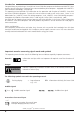
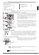
II 2 Operation The following data may be recalled with SmartTRAK: • Temperature curve • COM Workload curve • Alarms and attention messages English • Number of past dives • Total duration of past dives • Atmospheric pressure • Dive profile • Logbook 2.3 Switching on the display • automatically, on submerging in water or when adaptation to atmospheric pressure is necessary; • manually by bridging contacts on housing (B-E). • COM on opening the tank valve (if connected) (Tank pressure ≥ 8 bar / 116 psi).
2 Operation 2.6 Active backlight The display of Smart can be illuminated both on the surface and underwater. The backlight can be switched on by pressing Smart PRO above the display, and Smart COM at the right hand side of the display. The light will turn off automatically after 8 seconds or after the time selected via SmartTRAK. The backlight can only be activated if the computer display is on. 2.7 Switching off the display • automatically after 3 minutes without operation on the surface.
III Diving with Smart III 1 Terminology / Symbols 1.1 General terminology / Display during no-stop phase Oxygen toxicity CNS O2% Ascent rate (Only while ascending) No-stop phase Decompression phase Dive phase during which surfacing is allowed without stop. Dive phase during which surfacing is allowed only after decompression stops are completed.
1 Terminology / Symbols 1.3 Nitrox information (O2 information) For dives with compressed air in normal recreational diving, nitrogen is the decisive gas for the decompression calculations. When diving with Nitrox, the risk of oxygen toxicity rises with the increase of the fraction of oxygen and the increase of depth and can limit dive time and the maximum depth.
2 Attention messages and alarms III The audible attention messages (but not the alarms) can be switched off selectively with SmartTRAK. 2.2 Alarms WARNING Serious injury or death may result from failing to immediately respond to alarms given by Smart. 2.1 Attention messages Attention messages are communicated to the diver visually by symbols, letters or flashing figures. In addition, two short audible sequences can be heard (in an interval of 4 seconds) in two different frequencies under water.
3 Preparation for the dive 3.1 Setting the gas mixture Before every dive and after changing the tank, make sure that the setting of the gas mixture corresponds to the current mixture used. An incorrect setting causes Smart to miscalculate this particular dive. If the fraction of oxygen is set too low this can lead to oxygen poisoning without warning. If the value is set too high decompression sickness may occur. Inaccuracies in the calculations are carried over to repetitive dives.
4 Functions during the dive 4.2 Dive time % C DEPTH DIVE TIME The whole time spent below a depth of 0.8m (3 feet) is displayed as dive time in minutes. The time above 0.8m (3 feet) is counted as dive time only if the diver descends again below 0.8m (3 feet) within 5 minutes. While the dive time is running, the colons on the right of the figures are flashing in one second intervals. Maximum dive time displayed is 199 minutes. NO STOP DECO INFO MAX.
4 Functions during the dive WARNING The prescribed ascent rate must be observed at all times! Exceeding the prescribed ascent rate can lead to microbubbles in the arterial circulation which can lead to serious injury or death due to decompression sickness. • In case of an improper ascent Smart may require a decompression stop even within the no-stop phase because of the danger of microbubbles formation.
III 4 Functions during the dive 4.7 Oxygen toxicity (CNS O2%) % Smart calculates oxygen toxicity from depth values, time and the gas mixture and displays it in the location of the ascent rate. The toxicity is expressed in 1% increments of a maximum tolerated value (O2 clock). The symbol is % displayed together with the percentage. C DEPTH DIVE TIME English CNS O2% NO STOP DECO INFO MAX.
4 Functions during the dive TANK DATA 4.9 COM Remaining Bottom Time (RBT) RBT is the time left at the current depth until the point of time when the ascent must bar be started. The RBT is shown in the lower display. The RBT is calculated on the basis of the current tank pressure, breathing rate, the temperature, and the dive data RBT so far recorded. The RBT is based on the assumption that the tank pressure should amount to the set pressure (default 40 bar/600 psi) at the end of the dive.
% C DEPTH DIVE TIME CNS O2% % DECO STOP m DECO INFO MAX.DEPTH Decompression stop depth Decompression time DIVE TIME NO CNS O2% % DECO STOP m DECO INFO MAX.DEPTH The decompression alarm is activated if the decomDECOSTOP , the decompression stop duration and decompression stop depth begin to flash and an audible alarm goes off. Due to the formation of microbubbles, decompression can increase massively if a decompression stop is ignored.
5 Functions at the surface 5.1 End of a dive % C DEPTH DIVE TIME After reaching the surface (<0.8 m/3 ft) Smart remains in dive mode for 5 minutes. The delay allows for surfacing for a short period for orientation. After 5 minutes the dive is closed and it is entered into the logbook. DECO INFO MAX.DEPTH WARNING 5.2 Desaturation time % C DEPTH DIVE TIME NO h CNS O2% % DESAT h DECO INFO MAX.
6 Diving in mountain lakes % C DEPTH DIVE TIME DESAT h DECO INFO MAX.DEPTH III Smart measures the atmospheric pressure every 60 seconds even while the display is switched off. If the computer detects a sufficient increase in altitude, it switches on automatically and indicates the new altitude range (1-4) and the desaturation time. Desaturation time indicated at this moment refers to adaptation time at this altitude.
IV Diving with microbubble levels (MB) The following chapter deals with the characteristics of diving with microbubble levels (MB levels). For general information about displays and features of diving with Smart see chapter III. Microbubbles are tiny bubbles that can build up inside a diver's body during any dive and normally dissipate naturally during an ascent and on the surface after a dive.
2 Terminology IV This chapter will exclusively deal with terminology and display features used while diving with MB levels. All other features are described in chapter III (->11). Level stop phase MB no-stop phase Dive phase during which surfacing is possible without MB level stop. An MB level between L1 and L5 was chosen. Depth % C DEPTH DIVE TIME CNS O2% English 2.1 Display during microbubble (MB) no-stop phase Time % Dive time 21min MB no-stop time NO STOP DECO INFO MAX.
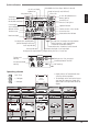
3 Preparation for a dive with microbubble levels (MB levels) 3.1 Setting the MB level To change the MB level Smart must be in user mode. … DEPTH 1. Bridge contacts B and + or B and – until until the symbol for MB levels appears. DIVE TIME 2. Confirm that you wish to change the displayed MB level by bridging B and E. + – 3. Change MB level by bridging contacts B and + or B and – . DECO INFO MAX.DEPTH DEPTH DIVE TIME 4. Confirm with B and E the selected MB level.
4 sec % C DEPTH WARNING DIVE TIME h CNS O2% % LEVELSTOP Level stop ignored Microbubble level reduced WARNING 4 sec C DEPTH DIVE TIME CNS O2% % LEVELSTOP The warning "Microbubble level reduced" is activated if the diver ascends more than 1.5m (5ft) above the required level stop. Smart then reduces the MB level, an attention beep* goes off and the new MB level will flash until the end of the dive. The level stop for the reduced MB level is now displayed.
4 Functions during the dive with microbubble levels 4.4 Level stop and deco stop Time Depth Microbubble level L5 L0 3m/10ft Deco stop duration Level stop duration Since level stops are more restrictive than decompression stops, when all decompression obligations have been observed the display changes from DECOSTOP LEVELSTOP to LEVELSTOP only.
V V Gauge mode Gauge mode is provided for those who prefer to utilize their own tables (technical diving) or for those who go freediving in addition to scuba diving. When in gauge mode, the Smart will only display time and depth information, however nitrogen tissue loading and oxygen exposure will be calculated just as they would be during a regular SCUBA dive. It is consequently very important that even when using the Smart in gauge mode, the correct value of your oxygen percentage is set -> 14.
Gauge mode After diving in gauge mode After a dive in gauge mode the display shows the following information based on the preset O2 mixture: Microbubble warning (do not dive)* ->20 % C DEPTH DIVE TIME NO NO h CNS O2% % No fly time ->20 Do not fly icon ->20 DESAT Prohibited altitude ->21 h MAX.DEPTH Oxygen toxicity ->20 DECO INFO Desaturation time ->20 * The duration of the microbubble warning is visible by entering the dive planner -> 29.
VI Dive planner Basis of the planning: If two or more divers using computers are planning a dive, planning for all divers has to be based on the dive computer showing the shortest no-stop times. Failure to do this may lead to serious injury or death from decompression sickness. WARNING 1 Planning a no-stop dive With the contacts B and – or B and – you can select the dive planner at the surface. NO DEPTH DIVE TIME NO h DECO INFO MAX.DEPTH MAX.
VI Dive planner 2 Leaving the dive planner With the contacts B and E (1-2 sec.) you can exit the dive planner. This also occurs after three minutes without operation.
CNS value at the end of the dive MB level reduced* Logbook icon Lowest temperature % C DEPTH DIVE TIME Diving in SOS mode S L O W Altitude range (if any) DECO Maximum depth % LOG h DECO INFO MAX.
VIII Appendix 1 Technical information Operating altitude: with decompression information: sea level up to approx. 4000 m (13120ft); w/o decompression, w/o RBT information: usable in gauge mode (at any altitude) Max. displayed depth: 120m (395 ft), resolution between 0.8 m and 99.9 m: 0.1 m, >99.9 m: 1m The resolution in feet is always 1 foot WARNING • Do not dive deeper than the limits given by the chosen fraction of oxygen (nitrogen narcosis, oxygen toxicity).
VIII VIII Appendix 3 COM Conversion of tank pressure The figure allows you to compare the information given by a conventional pressure gauge and by Smart COM at six different temperatures.
VIII Appendix 4 Warranty The warranty only covers dive computers which have been bought from an authorised SCUBAPRO UWATEC retailer. The warranty is given for a period of two years. Repairs or replacements during the warranty period do not increase the warranty period. In order to put forward a warranty claim: send the dive computer together with a dated receipt of the purchase to your authorised retailer or an authorised servicing point.
Active backlight __________________________ 10 Ascent rate _______________________ 11, 13, 15 Attention messages _______________________ 13 Battery alarm ____________________________ 13 Battery capacity, Checking the… ____________ 9 Battery lifetime ___________________________ 32 Beep, Switch off the… ____________________ 13 Bubbles, Warning of… _________________ 20, 29 CNS O2 __________________ 2, 3, 11, 12, 13, 31 Deco data during decompression phase ______ 11 Deco data during no-stop phase ____________ 1
SCUBAPRO UWATEC Americas (USA/Canada/Latin America) 1166 Fesler Street El Cajon, CA 92020 USA t: +1 619 402 1023 f: +1 619 402 1554 www.scubapro.com SCUBAPRO UWATEC France Les Terriers Nord 175 Allée Belle Vue F-06600 Antibes t: +33 (0) 4 92 91 30 30 f: +33 (0) 4 92 91 30 31 www.scubapro-uwatec.fr SCUBAPRO UWATEC Asia Pacific 1208 Block A, MP Industrial Center 18 Ka Yip St. Chai Wan Hong Kong t: +852 2556 7338 f: +852 2898 9872 www.scubaproasiapacific.
Smart TEC ® SWISS MADE BY UWATEC AG English Operating Manual
Safety considerations You must carefully read and understand this entire manual before using your Smart TEC. WARNING Diving has many inherent risks. Even if you follow the instructions of this manual in a careful manner, it is still possible that you may be seriously injured or die from decompression sickness, oxygen toxicity or some other inherent risk of scuba with Nitrox or compressed air.
Safety considerations • Always dive with back-up instruments. Make sure that you always use back-up instrumentation including a depth gauge, submersible pressure gauge, digital bottom timer or dive watch, and have access to decompression tables whenever diving with a dive computer. • Avoid repeated ascents and descents (yo yo diving). • Avoid repeated heavy workload while at depth. • Plan the dives to be shorter if they are made in cold water.
Introduction Congratulations on purchasing Smart TEC and welcome to UWATEC. From now on you will enjoy the assistance of the most extraordinary dive computer - equipped with UWATEC's most innovative technology while diving. Smart TEC enables you to use up to three different gas mixtures during the same dive. However, for an easy reading this manual mainly refers to dives with a single gas mixture. Information for diving with several gas mixtures is marked with ( ) or has been summarised in special chapters.
Quick reference I O2 mix icon (input) Gauge icon Logbook icon Dive planner icon English Microbubble level icon (input / MB level reduced) Do not fly Icon Do not dive icon Microbubble warning Dive time / No-fly time / SOS duration Current depth NO Service icon CNS O2% Ascent obligation Altitude sections Too fast ascent Icon for stopwatch and safety stop Logbook indicator Total ascent time / Dive number Ascent time icon Desaturation time indicator No-stop time / Decompression duration / MB no-stop time
List of chapters I Safety considerations Introduction Important remarks concerning signal words and symbols Quick reference / Operating scheme List of chapters ___________________________________2 ___________________________________4 II 1 System and operation System description ___________________________________8 ___________________________________8 2 Operation 2.1 Operating elements 2.2 SmartTRAK 2.3 Switching on the display 2.4 Checking the battery capacity 2.
6 Diving in mountain lakes 6.1 Altitude ranges 6.2 Prohibited altitude 6.3 Decompression dives in mountain lakes I __________________________________25 __________________________________25 __________________________________25 __________________________________25 IV Gauge mode __________________________________26 V 1 2 Diving with microbubble levels (MB) Comparison of dives with MB level L0 and MB level L5 Terminology 2.1 Display during microbubble (MB) no-stop phase 2.
II System and operation 1 System description TEC displays all important dive and decompression data and comes with a unique multichannel receiver, which can receive tank pressure data from up to 3 transmitters. Each transmitter is mounted at the high pressure (HP) outlet of the regulator, where it measures the tank pressure and radio transmits the information to TEC.
II System and operation To use the push buttons TEC must be switched on. Operation of the push buttons is divided into «press» and «press and hold (1 second)». The push buttons , and activate the following functions: Select the gas mixture (press) Confirm the gas mixture (press and hold) Activate the timer for safety stops (dive mode only, in depths < 6.
2 Operation 2.3 Switching on the display • automatically, on submerging in water or when adaptation to atmospheric pressure is necessary; • manually, by bridging contacts on housing (B-E). • When TEC is in state of rest no information is displayed but the atmospheric pressure is continuously monitored. If a higher altitude range is detected, TEC switches on for 3 minutes automatically. -> 25 NO CNS O2% NO DECO STOP LEVELSTOP NO STOP • TEC switches on by bridging the contacts B and E.
2.6 Active backlight The display of TEC can be illuminated both on the surface and underwater. The backlight can be activated by pushing and holding button for 1 second. The light will turn off automatically after 8 seconds or after the time selected via SmartTRAK. The backlight can only be activated if the computer display is on. WARNING The active backlight is no substitute for a dive torch. When diving at night or at increased depth we recommend the use of a dive torch. 2.
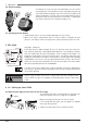
4 Setting up Smart TEC (transmitter and dive computer) 4.1 Mounting of transmitter Each individual pressure tank requires a separate transmitter. The transmitter is mounted at the high pressure (HP) outlet of the regulator’s first stage before the first dive. WARNING • Use air and Nitrox components in accordance with the law of the country. Procedure: HP (Adaptor) Do not hold the transmitter by its plastic part. Mount the transmitter at the HP oulet.
4.2 Pairing of transmitter and dive computer To receive the data of the transmitters, each transmitter must be assigned to one tank symbol and paired with TEC. Pairing is necessary: • before the first use of TEC with the transmitter; • if you use a new transmitter or a new computer; • after changing the battery; • if a different tank symbol (1, 2, or D) is to be paired to the transmitter; e.g. The transmitter is to be paired to tank symbol D instead of tank symbol 2.
4 Setting up Smart TEC • Pairing of transmitter and dive computer may already be carried out at home and need only be executed once, before the first use. • A transmitter can only be paired with a single tank symbol at a time. If you try to pair the same transmitter with a second tank symbol, the first pairing will automatically be deleted. • The pairing of transmitter and tank symbol will remain valid, even if the gas mixture is switched off (-> 34, switching off of gas mixtures).
III Diving with Smart TEC III The information on the display of TEC varies depending on the kind of dive and the dive phase. For information about diving with microbubble levels (MB levels) see chapter V ->28. Specific features of "Diving with more than one gas mixture", are described in chapter VI -> 32. 1.
1 Terminology / Symbols 1.3 Nitrox information (O2 information) For dives with compressed air in normal recreational diving, nitrogen is the decisive gas for the decompression calculations. When diving with Nitrox, the risk of oxygen toxicity rises with the increase of the fraction of oxygen and the increase of depth and can limit dive time and the maximum depth.
2 Attention messages and alarms III The audible attention messages (but not the alarms) can be selectively switched off with SmartTRAK. 2.2 Alarms WARNING Serious injury or death may result from failing to immediately respond to alarms given by TEC. 2.1 Attention messages Attention messages are communicated to the diver visually by symbols, letters or flashing figures. In addition, two short audible sequences can be heard (in an interval of 4 seconds) in two different frequencies under water.
3 Preparation for the dive 3.1 Setting the gas mixture and MOD WARNING Before every dive and after changing the tank, make sure that the settings for the gas mixtures correspond with the current mixtures used. An incorrect setting causes TEC to miscalculate this particular dive. If the fraction of oxygen is set too low this can lead to oxygen poisoning without warning. If the value is set too high decompression sickness may occur. Inaccuracies in the calculations are carried over to repetitive dives.
4 Functions during the dive 4.1 Immersion After immersion, starting at a depth of about 0.8 m (3 ft), TEC automatically selects gas mixture 1, all diving functions are monitored, i.e. depth and dive time displayed, maximum depth stored, saturation of tissues calculated, no-stop time or decompression prognosis determined, ascent rate controlled and displayed and the correctness of the decompression procedure supervised.
4 Functions during the dive WARNING The prescribed ascent rate must be observed at all times! Exceeding the prescribed ascent rate can lead to microbubbles in the arterial circulation which can lead to serious injury or death due to decompression sickness. • In case of an improper ascent TEC may require a decompression stop even within the no-stop phase because of the danger of microbubble formation.
4 Functions during the dive III 4.8 Oxygen toxicity (CNS O2%) TEC calculates oxygen toxicity from depth values, time and the gas mixture and displays it in the location of the ascent rate. The toxicity is expressed in 1% increments of a maximum tolerated value (O2 clock). The symbol is displayed together with the percentage. % Oxygen toxicity An audible attention signal goes off if oxygen toxiCNS O2% WARNING 4 sec CNS O2% WARNING CNS O2% NO STOP city reaches 75%.
4 Functions during the dive 4.10 Remaining Bottom Time (RBT) RBT is the time left at the current depth until the point of time when the ascent must be started. The RBT is calculated on the basis of the current tank pressure, breathing rate, the temperature, and the dive data so far recorded. The RBT is based on the assumption that the tank pressure should amount to the set pressure (default 40 bar/600 psi) at the end of the dive. Alterations can be made with SmartTRAK.
4 Functions during the dive CNS O2% DECO STOP % Decompression stop depth Decompression time CNS O2% DECO STOP Ignored decompression alarm Total time of ascent DECO STOP % Total time of ascent On entering the decompression phase, the arrow NO STOP disappears, the arrow DECOSTOP appears and an attention beep goes off. Right beside the arrow, the deepest decompression stage in metres (feet) is displayed.
5 Functions at the surface 5.1 End of a dive After reaching the surface (<0.8 m/3 ft) TEC remains in dive mode for 5 minutes. The delay allows for surfacing for a short period for orientation. After 5 minutes the dive is closed and it is entered into the logbook. % WARNING For the calculations of the desaturation and no-fly time it is assumed that the diver breathes air while on the surface. 5.
6 Diving in mountain lakes % Altitude range 1 Desaturation time Adaptation time Altitude ranges TEC measures the atmospheric pressure every 60 seconds even while the display is switched off. If the computer detects a sufficient increase in altitude, it switches on automatically and indicates the new altitude range (1-4) and the desaturation time. Desaturation time indicated at this moment refers to adaptation time at this altitude.
IV Gauge mode WARNING In gauge mode ALL audible and visual alarms and attention messages are turned off. This includes ascent speed, low tank pressure and interrupted signal from transmitter. In gauge mode TEC will display depth, dive time and tank pressure, the maximum depth is stored, ascent rate and tank pressure are monitored. By pressing you can switch from maximum depth to temperature and vice versa. You can also activate the stopwatch and check the split time.
IV Gauge mode III Stopwatch icon Hours Timing Minutes Seconds Stopwatch Example will start 00h00 00 automatically after 00h00 15 immersion 00h02 35 Automatically at the end of 00h00 00 dive In gauge mode, after immersion, TEC will automatically monitor the dive time and at the same time activate the stopwatch. If the gauge symbol and "on" are displayed (-> 26, point 1) the stopwatch can also be activated at the surface by pressing .
V Diving with microbubble levels (MB) The following chapter deals with the characteristics of diving with microbubble levels (MB levels). For general information about displays and features of diving with TEC see chapter III. Microbubbles are tiny bubbles that can build up inside a diver's body during any dive and normally dissipate naturally during an ascent and on the surface after a dive.
2 Terminology V This chapter will exclusively deal with terminology and display features used while diving with MB levels. All other features are described in chapter III (page 15). Level stop phase MB no-stop phase Dive phase during which surfacing is possible without MB level stop. MB level activated Level L2 is active English 2.
3 Preparation for a dive with microbubble levels (MB levels) 3.1 Setting the MB level To change the MB level TEC must be in user mode. 1. Bridge contacts B and + or B and – until the symbol for MB levels appears. 2. Confirm that you wish to change the displayed MB level by bridging B and E. + – 3. Change MB level by bridging contacts B and + or B and – . 4. Confirm with B and E the selected MB level. Without confirmation the display will disappear after 3 minutes and your entries will not be accepted.
4 sec WARNING CNS O2% LEVELSTOP V The attention message "Level stop ignored" is activated if the requested level stop is not observed. An attention beep* goes off, the arrow LEVELSTOP , the depth and duration of the ignored level stop begin flashing.
4 Functions during the dive with microbubble levels 4.4 Level stop and deco stop When the level stop depth equals the depth of the first obligatory decompression stop and if you are within 1.5m/5feet of the stop depth itself, TEC shows DECOSTOP and LEVELSTOP . The indicated duration refers to level stop duration.
VI Diving with more than one gas mixture VI Setting the gas mixture and the depth for changing the gas mixture During dives with more than one gas mixture the bottom mix Range of O2 fraction (tank 1) contains the lowest fraction of oxygen, while the deco mix (tank D) contains the highest fraction. The additional travel O2 fraction mix (tank 2) for dives with 3 gas mixtures holds a fraction of 100% oxygen that is between that of tank 1 and tank D.
VI Diving with more than one gas mixture Switching off gas mixtures Tanks which are not going to be used during the next dive (even though their fraction of oxygen has been defined) must be "switched off". This is achieved by switching off the appropriate gas mixture at TEC. Gas mixtures which have been switched off cannot be selected during the dive and TEC will ignore their transmitters. Tank 1 cannot be switched off.
Diving with more than one gas mixture VI Changing the gas mixture After immersion, TEC automatically selects gas mixture 1. 4 sec DECO STOP If during the ascent a diver reaches the depth WARNING requiring a change of gas mixture (MOD gas mix% ture D or 2), the imminent change is brought to the diver’s attention by an audible attention signal and the flashing of the tank symbol of the new oxygen fraction of tank 1 gas mixture, both lasting for 30 seconds.
VI Diving with more than one gas mixture 7. Above MOD for 100%, missed switch: now TEC-3 gives the same decompression prognosis as TEC1. TEC-4 gives the same decompression prognosis as TEC-2. 8. Again below the MOD for 100%: TEC-3 and TEC-4 again show credit for the presence of the 100% mix in their calculations 9. Above MOD for 100%, switch carried out: TEC-3 and TEC-4 show the tank pressure in the 100% tank. The RBT agrees. TEC-2 is not receiving anymore signals from the 50% tank and shows “- - -“.
VII Dive planner VII Basis of the planning: • • • • • • selected fraction of oxygen and MOD of all active gas mixtures selected microbubble level water temperature of the most recent dive altitude range (if any) status of saturation at the time the dive planner is selected assuming a normal workload of the diver and observance of the prescribed ascent rates • assumption: changes of gas mixture are performed at the selected MOD of mixtures 2 and D.
VII Dive planner 2 Planning a decompression dive 1. Activate the dive planner for a no-stop dive ->37. 2. Wait until the desired depth appears, then switch into decompression planning by bridging contacts B and E. TEC shows the bottom time (no-stop time + 1 minute) and the appropriate decompression information or level stop data respectively. 3. asks that you set the bottom time. This is done with contacts B and +, B and – respectively.
VIII Logbook VIII English 1 Survey A dive is entered in the logbook if the dive time is longer than 2 minutes. TEC records the profiles of about 100 hours of diving. This information can be transferred to a PC with the standard infrared interface (IrDA) and the Windows® software SmartTRAK. Up to 99 dives can be displayed directly on the dive computer.
IX Appendix 1 Technical information Operating altitude: with decompression information: sea level up to approx. 4000 m (13120ft); w/o decompression, w/o RBT information: usable in gauge mode (at any altitude) 120m (395 ft), resolution between 0.8 m and 99.9 m: 0.1 m, >99.9 m: 1m The resolution in feet is always 1 foot Max. displayed depth: WARNING • Do not dive deeper than the limits given by the chosen fraction of oxygen (nitrogen narcosis, oxygen toxicity).
IX Appendix IX Never touch the metal surface of the battery with bare fingers. The two battery poles must never be short circuited. Transmitter Battery CR2450 Transmitter Cap English WARNING HP port o-ring 8.73 x 1.78 mm Transmitter screws PT®KA 30 x 16 mm Transmitter cap o-ring 26.00 x 2.00 mm Procedure: To replace the battery you need a Phillips screwdriver and a clean cloth.
IX Appendix WARNING 10. The transmitter cap will only fit in one position. Check the proper position of the guide slots on the electronic support and in the transmitter cap. Slide the transmitter cap carefully back into its proper position. 11. Do not overtighten the screws! Fasten the transmitter cap with the 3 screws. 12. Mount the transmitter on the HP outlet of the first stage of the regulator and check transmission and pairing.
IX Excluded are faults or defects due to: • excessive wear and tear; • exterior influences, e.g. transport damage, damage due to bumping and hitting, influences of weather or other natural phenomena; • servicing, repairs or the opening of the dive computer by anybody not authorised by the manufacturer. This especially concerns the change of battery; • pressure tests which do not take place in water; • diving accidents; • improper placement of the transmitter cap.
SCUBAPRO UWATEC Americas (USA/Canada/Latin America) 1166 Fesler Street El Cajon, CA 92020 USA t: +1 619 402 1023 f: +1 619 402 1554 www.scubapro.com SCUBAPRO UWATEC France Les Terriers Nord 175 Allée Belle Vue F-06600 Antibes t: +33 (0) 4 92 91 30 30 f: +33 (0) 4 92 91 30 31 www.scubapro-uwatec.com SCUBAPRO UWATEC Asia Pacific 1208 Block A, MP Industrial Center 18 Ka Yip St. Chai Wan Hong Kong t: +852 2556 7338 f: +852 2898 9872 www.scubaproasiapacific.
Deutsch English Français Operating Manual Smart Z ® SWISS MADE BY UWATEC AG
Safety considerations You must carefully read and understand this entire manual before using your new computer. WARNING Diving has many inherent risks. Even if you follow the instructions of this manual in a careful manner, it is still possible that you may be seriously injured or die from decompression sickness, oxygen toxicity or some other inherent risk of scuba with Nitrox or compressed air.
• Always dive with back-up instruments. Make sure that you always use back-up instrumentation including a depth gauge, submersible pressure gauge, digital bottom timer or dive watch, and have access to decompression tables whenever diving with a dive computer. • Avoid repeated ascents and descents (yo yo diving). • Avoid repeated heavy workload while at depth. • Plan the dives to be shorter if they are made in cold water.
Introduction Congratulations on purchasing a Smart Z dive computer and welcome to UWATEC. From now on you will enjoy the assistance of the most extraordinary dive computer - equipped with UWATEC's most innovative technology - while diving. We thank you for choosing this computer and we hope you will enjoy safe dives in the future! Further information on UWATEC Smart dive computers and other products by UWATEC can be found on our web page at www.uwatec.com.
Quick reference I O2 mix icon (input) Temperature Microbubble level icon (input / MB level reduced) Current depth Dive time / No-fly time / SOS duration NO Service icon Logbook indicator Total ascent time / Dive number Ascent time icon Desaturation time indicator No-stop time / Decompression duration / MB no-stop time Level stop duration / Duration of Microbubble Warning Desaturation duration / Duration of surface interval NO CNS O2% Gauge icon Altitude sections Too fast ascent Ascent obligation
List of chapters I Safety considerations ___________________________________ 2 Introduction ___________________________________ 4 Important remarks concerning signal words and symbols ______________________________ 4 Quick reference / Operating scheme ___________________________________ 5 List of chapters ___________________________________ 6 II 1 System and operation System description ___________________________________ 8 ___________________________________ 8 2 Operation 2.1 Operating elements 2.
6 Diving in mountain lakes 6.1 Altitude ranges 6.2 Prohibited altitude 6.3 Decompression dives in mountain lakes I __________________________________ 25 __________________________________ 25 __________________________________ 25 __________________________________ 25 IV Gauge mode __________________________________ 26 V 1 2 Diving with microbubble levels (MB) Comparison of dives with MB level L0 and MB level L5 Terminology 2.1 Display during microbubble (MB) no-stop phase 2.
II System and operation 1 System description Smart Z displays all important dive and decompression data and comes with a unique receiver which can receive tank pressure data from a transmitter. Mounted at the high pressure (HP) outlet of the regulator, the transmitter measures the tank pressure and radio transmits the information to Smart Z. UWATEC's specially patented transmission process prevents interference and ensures continuous and reliable reception.
II II System and operation 2.2 SmartTRAK With SmartTRAK you can transfer dive data to a personal computer and graphically display the data. • Unit system metric/imperial • Audible attention signal suppression selective • Gauge mode on / off • Depth alarm 5 - 100 m (20 - 330 feet) • Backlight illumination duration 2-12 sec. • Maximum partial pressure of oxygen (ppO2 max) 1-1.95 bar • Time limit to reset the O2 % mix to air no reset / 1 - 48 hrs.
2 Operation 2.3 Switching on the display • automatically, on submerging in water or when adaptation to atmospheric pressure is necessary; • manually, by bridging contacts on housing (B-E). • When Smart Z is in state of rest no information is displayed but the atmospheric pressure is continuously monitored. If a higher altitude range is detected, Smart Z switches on for 3 minutes automatically -> 25. NO NO CNS O2% DECO STOP LEVELSTOP NO STOP • Smart Z switches on by bridging the contacts B and E.
II 2 Operation / 3 SOS mode The display of Smart Z can be illuminated both on the surface and underwater. The backlight can be activated by pressing on top of the case. The light will turn off automatically after 8 seconds or after the time selected via SmartTRAK. The backlight can only be activated if the computer display is on. 2.7 Switching off the display On the surface Smart Z switches off automatically after 3 minutes without operation.
4 Setting up Smart Z (transmitter and dive computer) 4.1 Mounting of transmitter The transmitter is mounted at the high pressure (HP) outlet of the regulator’s first stage before the first dive. WARNING Use air and Nitrox components in accordance with the law of the country. Procedure: HP (Adaptor) Do not hold the transmitter by its plastic part. Mount the transmitter at the HP oulet. If the threads do not match, you can get a fitting adaptor at your diving equipment retailer.
II 4 Setting up (transmitter and dive computer) 4.2 Pairing of transmitter and dive computer To receive the data of the transmitter, the transmitter itself must be paired with Smart Z. Pairing is necessary: English • before the first use of Smart Z with the transmitter; • if you use a new transmitter or a new computer; • after changing the battery. Pairing procedure: 1. Shut the valve, depressurise the regulator and wait for 15 seconds. 2. Switch on Smart Z (bridge contacts B and E). 3.
4 Setting up Smart Z How to check if transmitter and computer are paired correctly: % Pairing ok % Pairing present, no pressure data available % Pairing not present 14 1. 2. 3. 4. Switch on the computer manually (B and E) Move the computer into transmitting range of the transmitter. Open the tank valve. The transmitter switches on automatically. Check the display: Pairing has been carried out correctly if the pressure is displayed within 5-10 seconds.
III Diving with Smart Z III 1 Terminology / Symbols For information about diving with microbubble levels (MB levels) see chapter V ->28. 1.1 General terminology / Display during no-stop phase Oxygen toxicity CNS O2% Ascent rate (Only while ascending) Dive time Duration of the dive (min) Decompression phase Dive phase during which surfacing is allowed without stop. Dive phase during which surfacing is allowed only after decompression stops are completed.
1 Terminology / Symbols 1.3 Nitrox information (O2 information) For dives with compressed air in normal recreational diving, nitrogen is the decisive gas for the decompression calculations. When diving with Nitrox, the risk of oxygen toxicity rises with the increase of the fraction of oxygen and the increase of depth and can limit dive time and the maximum depth.
2 Attention messages and alarms III The audible attention messages (but not the alarms) can be selectively switched off with SmartTRAK. 2.2 Alarms WARNING Serious injury or death may result from failing to immediately respond to alarms given by Smart Z. 2.1 Attention messages Attention messages are communicated to the diver visually by symbols, letters or flashing figures. In addition, two short audible sequences can be heard (in an interval of 4 seconds) in two different frequencies under water.
3 Preparation for the dive 3.1 Setting the gas mixture and MOD Before every dive and after changing the tank, make sure that the settings for the gas mixture correspond with the current mixture used. An incorrect setting causes Smart Z to miscalculate this particular dive. If the fraction of oxygen is set too low this can lead to oxygen poisoning without warning. If the value is set too high decompression sickness may occur. Inaccuracies in the calculations are carried over to repetitive dives.
4 Functions during the dive 4.2 Dive time Dive time NO STOP The whole time spent below a depth of 0.8m (3 feet) is displayed as dive time in minutes. The time above 0.8m (3 feet) is counted as dive time only if the diver descends again below 0.8m (3 feet) within 5 minutes. While the dive time is running, the colons on the right of the figures are flashing in one second intervals. Maximum dive time displayed is 199 minutes.
4 Functions during the dive WARNING The prescribed ascent rate must be observed at all times! Exceeding the prescribed ascent rate can lead to microbubbles in the arterial circulation which can lead to serious injury or death due to decompression sickness. • In case of an improper ascent Smart Z may require a decompression stop even within the no-stop phase because of the danger of microbubble formation.
III 4 Functions during the dive 4.8 Oxygen toxicity (CNS O2%) Smart Z calculates oxygen toxicity from depth values, time and the gas mixture and displays it in the location of the ascent rate. The toxicity is expressed in 1% increments of a maximum tolerated value (O2 clock). The symbol "CNS O2" is displayed together with the percentage. % Oxygen toxicity An audible attention signal goes off if oxygen tox4 sec WARNING icity reaches 75%. The symbol "CNS O2" flashes and the ascent arrow appears.
4 Functions during the dive 4.10 Remaining Bottom Time (RBT) RBT is the time left at the current depth until the point of time when the ascent must be started. The RBT is calculated on the basis of the current tank pressure, breathing rate, the temperature, and the dive data so far recorded. The RBT is based on the assumption that the tank pressure should amount to the set pressure (default 40 bar/600 psi) at the end of the dive. Alterations can be made with SmartTRAK.
CNS O2% DECO STOP Decompression stop depth Decompression time On entering the decompression phase, the arrow NO STOP disappears, the arrow DECOSTOP appears and an attention beep goes off. Right beside the arrow, the deepest decompression stage in metres (feet) is displayed. Next to the decompression stop depth, the decompression stop duration of the displayed stage appears in minutes. The display "3m 7:" means that a decompression stop of 7 minutes at a depth of 3m has to be made.
5 Functions at the surface 5.1 End of a dive After reaching the surface (<0.8 m/3 ft) Smart Z remains in dive mode for 5 minutes. The delay allows for surfacing for a short period for orientation. After 5 minutes the dive is closed and it is entered into the logbook. % WARNING For the calculations of the desaturation and no-fly time it is assumed that the diver breathes air while on the surface. 5.
6 Diving in mountain lakes Altitude range 1 Desaturation time Adaptation time Altitude ranges III Smart Z measures the atmospheric pressure every 60 seconds even while the display is switched off. If the computer detects a sufficient increase in altitude, it switches on automatically and indicates the new altitude range (1-4) and the desaturation time. Desaturation time indicated at this moment refers to adaptation time at this altitude.
IV Gauge mode WARNING In gauge mode ALL audible and visual alarms and attention messages are turned off. This includes ascent speed, low tank pressure and interrupted signal from transmitter. In gauge mode Smart Z will display depth, dive time and tank pressure, the maximum depth is stored, ascent rate and tank pressure are monitored. Gauge mode does not support the calculation of no-stop time or the supervision of decompression. Supervision of ppO2 max and CNS O2% will also be switched off.
IV IV Gauge mode After diving in gauge mode Smart Z shows the remaining time span during which it cannot be used in computer mode. Once the waiting period is over, the gauge mode can be switched off manually ->26. NO English The no-fly time after diving in gauge mode is 48 hours. Desaturation time will not be displayed.
V Diving with microbubble levels (MB) The following chapter deals with the characteristics of diving with microbubble levels (MB levels). For general information about displays and features of diving with Smart Z see chapter III. Microbubbles are tiny bubbles that can build up inside a diver's body during any dive and normally dissipate naturally during an ascent and on the surface after a dive.
2 Terminology V This chapter will exclusively deal with terminology and display features used while diving with MB levels. All other features are described in chapter III (page 15). MB no-stop phase Dive phase during which surfacing is possible without MB level stop. Depth MB level An MB level between L1 and L5 was chosen. CNS O2% English 2.
3 Preparation for a dive with microbubble levels (MB levels) 3.1 Setting the MB level To change the MB level Smart Z must be in user mode. 1. Bridge contacts B and + or B and – until the symbol for MB levels appears. 2. Confirm that you wish to change the displayed MB level by bridging B and E. + – 3. Change MB level by bridging contacts B and + or B and – . 4. Confirm with B and E the selected MB level. Without confirmation the display will disappear after 3 minutes and your entries will not be accepted.
4 sec WARNING CNS O2% LEVELSTOP Level stop ignored WARNING Microbubble level reduced 4 sec CNS O2% LEVELSTOP V The attention message "Level stop ignored" is activated if the requested level stop is not observed. An attention beep* goes off, the arrow LEVELSTOP , the depth and duration of the ignored level stop begin flashing.
4 Functions during the dive with microbubble levels 4.4 Level stop and deco stop Depth Time 3m/10ft Microbubble level L5 L0 Deco stop duration Level stop duration L0 L5 Since level stops are more restrictive than decompression stops, when all decompression obligations have been observed the display changes from DECOSTOP LEVELSTOP to LEVELSTOP only.
VI Dive planner VI Basis of the planning: WARNING • • • • • • selected fraction of oxygen and MOD selected microbubble level water temperature of the most recent dive altitude range (if any) status of saturation at the time the dive planner is selected assuming a normal workload of the diver and observance of the prescribed ascent rates If two or more divers using computers are planning a dive, planning for all divers has to be based on the dive computer showing the shortest no-stop times.
VI Dive planner 2 Planning a decompression dive 1. Activate the dive planner for a no-stop dive ->33. 2. Wait until the desired depth appears, then switch into decompression planning by bridging contacts B and E. Smart Z shows the bottom time (no-stop time + 1 minute) and the appropriate decompression information or level stop data respectively. 3. "Add" asks that you set the bottom time. This is done with contacts B and +, B and – respectively.
VII Logbook VII English 1 Survey A dive is entered in the logbook if the dive time is longer than 2 minutes. Smart Z records the profiles of about 100 hours of diving. This information can be transferred to a PC with the standard infrared interface (IrDA) and the Windows® software SmartTRAK. Up to 99 dives can be displayed directly on the dive computer.
VIII Appendix 1 Technical information Operating altitude: with decompression information: sea level up to approx. 4000 m (13120ft); w/o decompression, w/o RBT information: usable in gauge mode (at any altitude) 120m (395 ft), resolution between 0.8 m and 99.9 m: 0.1 m, >99.9 m: 1m The resolution in feet is always 1 foot. Max. displayed depth: WARNING • Do not dive deeper than the limits given by the chosen fraction of oxygen (nitrogen narcosis, oxygen toxicity).
VIII VIII Appendix Never touch the metal surface of the battery with bare fingers. The two battery poles must never be short circuited. Transmitter Battery CR2450 Transmitter Cap English WARNING HP port o-ring 8.73 x 1.78 mm Transmitter screws PT®KA 30 x 16 mm Transmitter cap o-ring 26.00 x 2.00 mm Procedure: To replace the battery you need a Phillips screwdriver and a clean cloth. WARNING 1. 2. 3. 4. 5. 6.
VIII Appendix WARNING 10. The transmitter cap will only fit in one position. Check the proper position of the guide slots on the electronic support and in the transmitter cap. Slide the transmitter cap carefully back into its proper position. 11. Do not overtighten the screws! Fasten the transmitter cap with the 3 screws. 12. Mount the transmitter on the HP outlet of the first stage of the regulator and check transmission and pairing.
5 FCC This device complies with part 15 of the FCC Rules. Operation is subject to the following two conditions: (1) This device may not cause harmful interference, and (2) this device must accept any interference received, including interference that may cause undesired operation.
SCUBAPRO UWATEC Americas (USA/Canada/Latin America) 1166 Fesler Street El Cajon, CA 92020 USA t: +1 619 402 1023 f: +1 619 402 1554 www.scubapro.com SCUBAPRO UWATEC France Les Terriers Nord 175 Allée Belle Vue F-06600 Antibes t: +33 (0) 4 92 91 30 30 f: +33 (0) 4 92 91 30 31 www.scubapro-uwatec.com SCUBAPRO UWATEC Asia Pacific 1208 Block A, MP Industrial Center 18 Ka Yip St. Chai Wan Hong Kong t: +852 2556 7338 f: +852 2898 9872 www.scubaproasiapacific.
Quick reference Smart TEC O2 mix icon (input) Gauge icon Logbook icon Dive planner icon Microbubble level icon (input / MB level reduced) Do not fly Icon Do not dive icon Microbubble warning Dive time / No-fly time / SOS duration Current depth NO Service icon CNS O2% Ascent obligation Altitude sections Too fast ascent Maximum depth Temperature Microbubble level Maximum Operating Depth (MOD) Icon for stopwatch and safety stop Logbook indicator Total ascent time / Dive number Ascent time icon Desaturatio
Operating scheme Smart TEC Select (press) and confirm (press and hold) gas mixtures Start / Confirmation / Enter Activate the timer for safety stops (dive mode only, in depths < 6.5 m / 20 ft) (press) Operate the stopwatch (gauge mode only) (press) Set a bookmark (press) + / Navigate – / Navigate On the surface TEC switches off automatically after 3 minutes without operation.