ASTRA 4000RS SERIES VEHICLE SECURITY SYSTEM WITH REMOTE START WITH SEPERATE LOCK/UNLOCK BUTTONS PRODUCT MANUAL
Limited Lifetime Warranty This vehicle security system is warranted to the original purchaser, to be free from defects in material and workmanship. The manufacturer will repair or replace at its option, and free of charge for the first twelve (12) months, any part that proves defective in material or workmanship under normal installation, use, and service, provided the product is returned to the manufacturer freight prepaid.
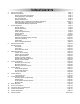
Table of Contents 1. 2. 3. 4. 5. 6. 7. 8. 9. 10. 11. 12. 13. 14. 15. About Your System . . . . . . . . . . . . . . . . . . . . . . . . . . . . . . . . . . . . . . . . . . . . . . . . . . . . . . .Page 1 Remote Transmitters . . . . . . . . . . . . . . . . . . . . . . . . . . . . . . . . . . . . . . . . . . . . . . . . . . . . . .Page 2 Remote Transmitter Description . . . . . . . . . . . . . . . . . . . . . . . . . . . . . . . . . . . . . . . . . .Page 2 Adding/Replacing Transmitters . . . . . . . .
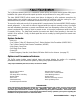
About Your System The ScyTek Astra 4000RS SERIES is a combination vehicle security and remote starting system. With proper installation this system will provide superior protection and performance for many years to come. The Astra 4000RS SERIES built-in remote start feature is designed to offer maximum convenience by remote starting your vehicle’s engine, turning on the heater/air conditioner, and then running for a predetermined time to provide a comfortable environment once you enter your vehicle.
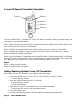
Remote Transmitters Standard Remote Transmitter Description LED Button 1 Button 2 Button 5 Button 3 Button 4 The Astra 4000RS Series comes equipped with the 5-button Remote Transmitters used to control system operations. Button 1 Arms the system and when held for 5 seconds, activates the system’s Panic feature. Button 1 also locks the doors when the system is in Valet Mode. Button 2 Disarms the system. Pressing Button 2 again operates the Passenger Unlock feature (if installed).
Adding/Replacing Transmitters To replace lost or stolen transmitters or to add additional transmitters into the system, have all desired transmitters ready and follow the steps below. Note: Up to 4 one-way transmitters can be programmed to operate the system. Any previously stored transmitter codes will be erased if they are not programmed within the following sequence. To program the transmitter(s): 1. Turn on the ignition key On, Off, On, Off, and back On. (Key On 3 times) · The siren will chirp 3 times.
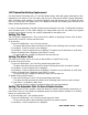
2-way LCD Remote Transmitter Description Button 1 Button 2 Button 3 Button 4 Button 5 The Astra 4000RS-2W-1 is supplied one 2-way LCD remote transmitter, offering increased range and confirmation of any activated features. Button 1 Arms the system and when held for 5 seconds, activates the system’s Panic feature. Button 1 also locks the doors when the system is in Valet Mode. Button 2 Disarms the system. Button 2 also unlocks the doors when the system is in Valet Mode.
LCD Transmitter Battery Replacement Your Astra Remote Transmitter uses a 1.5 volt AAA alkaline battery, which will require replacement in time. Depending on the amount of use, the battery may last up to three months before it needs replacement. When the battery needs replacing, the system’s operating range will decrease, the LCD display will show only one of three bars in the battery icon, or the display and sounds may suddenly stop and start as the battery voltage drops below minimum.
4. When the desired time is displayed, press Button 5 to store. · The remote will play a melody to indicate the alarm clock has been set. To disable the automatic start / auto activate function: 1. Press and hold Buttons 2 and 3 until the remote beeps four times. · The fan and clock will be shown indicating automatic start mode is entered. 2. Press Button 1 to disable the alarm clock. · The remote will play a melody to indicate the alarm clock has been disabled.
The PSV or passive function allows the passive arming mode to be enabled or with the transmitter. Note: This feature may not be available on all systems. To enable or disable the passive arming mode: 1. Press and hold Button 5 until the display shows PSV. · The transmitter will beep four times. 2. Release Button 5. · The transmitter will beep once. · The LCD panel will play a tone if the sounds are enabled or "off" will be displayed if the chirps are disabled.
System Operation Remote Arming The system monitors 5 independent areas (zones) while armed: doors, hood, trunk, shock sensor, optional sensor input, and the network port for future expansion. To Arm the System: 1. Turn off the ignition. 2. Press Button 1. · The siren will chirp once.* · The doors will lock. · The parking lights will flash once. · The LED will turn on red, to indicate the starter defeat is activate. 3.
Tamper Alert If the system was triggered while away, the LED will flash to indicate which zone triggered the system after disarming and turning on the ignition. The LED indication will repeat 8 times.
Panic Mode In the event of an emergency the transmitter’s remote Panic feature can be used to instantly trigger the alarm. To activate the Panic Mode: 1. Press and hold Button 1 for five seconds. · The alarm will sound. · The parking lights will flash. · The doors will unlock* allowing access to the vehicle. 2. Press Button 2 to stop Panic Mode. * If the ignition is on when the Panic feature is activated, the doors will lock for personal safety.
To set the Emergency Override Code: 1. Turn on ignition. 2. Within 5 seconds, press the valet switch 5 times. · The siren will provide one long chirp, indicating that you have entered Programming. 3. Press the valet switch 6 times. · The siren will chirp each time the valet switch is pressed. 4. Within 5 seconds, press Button 3 on the transmitter. · The siren will chirp 3 times. 5. Press the valet switch the number of times equal to the desired code (from 1-15). 6. Turn off the ignition then arm the system.
Remote Start Features Remote Starting To Remote Start the System: 1. Be sure the system is not in Valet Mode. 2. Press and hold Button 4 for three seconds. · The parking lights will flash 4 times and turn on. · The Siren will chirp 4 times. · The engine will start and run for the duration of its programmed Run Time.* · The heater or air conditioner will turn on (if turned on prior to exiting the vehicle). *If the engine fails to start on the first attempt, it will repeat the starting procedure 2 more times.
Automatic Start Mode The Automatic Start Mode allows the vehicle to automatically start the vehicle every one or two hours and run for the preset Run Time. To turn on Auto Starting: 1. Turn Ignition switch Off and wait for 3 seconds. 2. Turn Ignition switch On and Off three times ending with Ignition in Off position 3. Press and release the Valet switch immediatly. Parking lights will flash indicating that the Auto Start mode has been activated.
Extended Features Ignition Door Locking For added safety, the Ignition Door Locking feature allows vehicles equipped with power door lock systems to automatically lock the doors when the ignition is turned on. If a door is open when the ignition is turned on, the Ignition Door Locking feature is disabled to protect against locking the keys inside the vehicle. Ignition Door Unlocking For added convenience, this feature automatically unlocks the doors after the ignition key is turned off.
System Installation 1. 2. Thoroughly read and become familiar with the installation instructions before beginning the installation. Review system contents: Main Unit Two 5-Button Remote Transmitters (4000RS) One 5-Button & One LCD Two-Way Transmitter (4000RS-2W-1) Siren Shock Sensor Harnesses • • • • • • 6-Wire starter harness/Relay Module 16-Pin main harness 4-Pin shock sensor harness 3-Pin door lock harness LED harness Override Switch harness 3. 4.
Mounting the Control Unit The control unit must only be mounted in the interior of the vehicle. Do not mount the main unit in the engine compartment. Choose a mounting location that will not be easily accessible to a thief, and will not interfere with the operation of any vehicle components such as foot pedals, steering column, air vents, seat rails, etc. Do not mount the control unit until after setting the internal jumpers and performing a complete operation check of the system.
System Wiring 6-Wire Starter Harness Pin 1 RED - A: Main Power Input A (+). Connect to the battery or constant power wire at the ignition switch with a minimum 30 Amp supply. Remove the fuse until the installation is complete and all wiring is checked. Pin 2 RED - B: Main Power Input B (+). Connect to the battery or constant power wire at the ignition switch with a minimum 30 Amp supply.
Pin 12 ORANGE: Armed Output (-) 500 mA. The Orange wire provides a ground output while armed to activate a relay for starter defeat and anti-grind protection. Pin 13 GRAY: Auxiliary 1 Output (-) 500 mA. Connect to a relay for an optional feature such as trunk release, etc. This output may be programmed for momentary, timed, or latched operation. Pin 14 GREEN/WHITE: Brake Input (+). Connect to the wire that shows +12V when pressing the brake.
Jumper Settings Jumper Selection Carefully separate the top and bottom halves of the main unit case. Once the cover is removed, the parking light polarity jumper will be visible next to the parking light relay. Set the jumper for the correct polarity output as described below, then reassemble the main unit case. Parking Light Output. Selects the polarity (+/-) for the output of the on-board Parking Light relay.
System Programming Entering System Programming The system programming is compatible with both the LCD transmitter or the standard AM transmitter. To enter System Programming: 1. Turn on ignition. 2. Within 5 seconds, press the valet switch 5 times. · The siren will provide three chirps, indicating that you have entered Programming. 3. Press the valet switch the number times equal to the System Parameter you want to change. · The siren will chirp each time the valet switch is pressed. 4.
Branch Feature Button 1 (default) Button 2 Button 3 1. Arm Mode Manual Arming Passive Arming 2. Auto Rearming Mode Disabled Enabled 3. Arming Chirps Siren Chirps On Silent Siren & Horn Chirps On 4. Warn-Away Pager Report Enabled Disabled 5. Extended Parking Lights On Off 6. Ignition Door Locking On Off Set Override Code 7. Ignition Door Unlocking On Off 8. Door Unlock Pulse Single Double 9. Door Lock Pulse Length 1 second 3 seconds 0.1 seconds 10. Passive Door Locking Disabled Enabled 11.
13. 14. 15. 16. 17. 18. 19. 20. 21. 22. 23. Momentary operation provides an output for as long as the transmitter button is pressed. Timed operation provides an output that turns on for 10 seconds each time the transmitter button is pressed. If the button is pressed again during the 30 seconds, the output will turn off. Latched operation provides an output that turns on when the transmitter button is pressed and remains on until the transmitter button is pressed again. Disarm with Auxiliary 1.
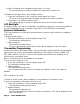
Relay Diagrams Positive Dome Light Activation Negative Dome Light Activation Positive Horn Honk Negative Horn Honk Negative Glow Plug Starter Defeat/Anti-Grind Astra 4000RS Series - Page 23
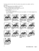
Door Lock Diagrams Follow the diagrams below for connecting basic door lock systems. For Two Stage door lock systems (separately unlocks driver and passenger doors) see following pages.
Two Stage Door Lock Diagrams The Astra 4000RS Series can be wired for the Passenger Unlock output feature, allowing Two Stage Door Lock operation. When connected as shown below, disarming the system will unlock only the driver’s door. Pressing the Aux 1 button will unlock all doors.
Two Stage Door Lock Diagrams cont’d Two Stage Reverse Polarity Aux 1 output (gray wire) Two Stage Adding Actuators Aux 1 output (gray wire) Page 26 - Astra 4000RS Series
Technical Information FCC ID: OARRXAM2000 This device complies with Part 15 of FCC Rules. Operation is subject to the following two conditions: 1) This device may not cause harmful interference.
Wiring Diagram Antenna Shock Sensor Green - Lock Out (-) 500ma N.A.