ASTRA 777 WITH SEPERATE LOCK/UNLOCK BUTTONS VEHICLE SECURITY SYSTEM PRODUCT MANUAL
Limited Lifetime Warranty This vehicle security system is warranted to the original purchaser, to be free from defects in material and workmanship. The manufacturer will repair or replace at its option, and free of charge for the first twelve (12) months, any part that proves defective in material or workmanship under normal installation, use, and service, provided the product is returned to the manufacturer freight prepaid.
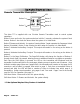
Table of Contents 1. About Your System . . . . . . . . . . . . . . . . . . . . . . . . . . . . . . . . . . . . . . . . . . . . . . . . . . . . . .Page 1 2. 2-way LCD Remote Transmitters . . . . . . . . . . . . . . . . . . . . . . . . . . . . . . . . . . . . . . . . . . . . . . . . . . . . . . . . .Page 2 2-way LCD Remote Transmitter Description . . . . . . . . . . . . . . . . . . . . . . . . . . . . . . . . . . . . . . . . . . . .Page 2 Adding/Replacing 2-way LCD Transmitters . . . . . . . . . . . . . .
About Your System Congratulations on your purchase of this state-of-the-art vehicle security system from ScyTek Electronics. With proper installation this system will provide superior protection and performance for many years to come.
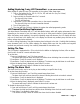
2-way LCD Remote Transmitter Description Button 1 Button 2 Button 3 Button 4 Button 5 The Astra’s 777 2-way LCD remote transmitter is offering increased range and confirmation of any activated feature. Page 1 Button 1 Arms and Locks* the system and when held for 5 seconds, activates the system’s Panic feature. Button 1 also locks the doors when the system is in Valet Mode. Button 2 Disarms and Unlocks* the system. Pressing Button 2 again operates the Passenger Unlock feature (if installed).
Adding/Replacing 2-way LCD Transmitters (2 LCD remotes maximum) When adding an optional 2-way LCD transmitter to the system, follow these steps: 1. Turn on the ignition key On, Off, On, Off, On, Off, and back On. (Key On 4 times) · The siren will chirp 4 times. 2. Press and hold the Override switch for 5 seconds. · The siren will chirp 4 times. · The LED will illuminate. 3. Press Button 1 on the first transmitter, then on the second transmitter. · The siren will chirp once for each transmitter learned. 4.
LCD Backlight Transmitter Button 5 is used for confirmation, transmitter programming, as well as activation of the LCD backlighting for use in the dark. Press button 5 to activate the LCD backlight. System Confirmation The 2-way transmitter's confirmation feature allows the current vehicle status to be displayed at any time. To display system status: 1. Press and hold Button 5 until the display shows CON. · The transmitter will beep once. 2. Release Button 5. · The transmitter will beep once.
VLT Valet mode function sets and resets the security system valet mode. * this function is enabled only when the security system is disarmed Set or reset the Valet mode: 1. Press and hold Button 6 until the display shows VLT. · The transmitter will beep six times. 2. Release Button 5. · The LCD panel will play a tone if the Valet mode was set “V" will be displayed indicating that the system is in Valet mode. · The transmitter will beep twice if the Valet mode was reset.
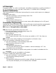
Remote Transmitters Remote Transmitter Description LED Button 1 Button 2 Button 5 Button 3 Button 4 The Astra 777 is supplied with one 5-button Remote Transmitter used to control system operations. Button 1 Arms and Locks* the system and when held for 5 seconds, activates the system’s Panic feature. Button 1 also locks the doors when the system is in Valet Mode. Button 2 Disarms and Unlocks* the system. Pressing Button 2 again operates the Passenger Unlock feature (if installed).
Adding/Replacing One-Way Transmitters To replace lost or stolen transmitters or to add additional transmitters into the system, have all desired transmitters ready and follow the steps below. Note: Up to 4 one-way transmitters can be programmed to operate the system. Any previously stored transmitter code will be erased if it is not programed within the following sequence. To program the transmitter(s): 1. Turn on the ignition key On, Off, On, Off, and back On. · The siren will chirp 3 times. 2.
System Operation Remote Arming The system monitors 4 independent areas (zones) while armed: doors, hood/trunk, shock sensor and optional sensor input. To Arm the System: 1. Turn off the ignition. 2. Press Button 1. · The siren will chirp once.* · The doors will lock. · The parking lights will flash once. · The LED will turn on, to indicate the starter defeat is activated. 3. 5 seconds after Arming: · The LED will start blinking to indicate that the doors and hood/trunk inputs are being monitored.
Tamper Alert If the system was triggered while away, the LED will flash to indicate which zone triggered the system after disarming and turning on the ignition. The LED indication will repeat 8 times.
Panic Mode In the event of an emergency, the transmitter’s remote Panic feature can be used to instantly trigger the alarm. To activate the Panic Mode: 1. Press and hold Button 1 for 5 seconds. · The alarm will sound. · The parking lights will flash. · The doors will unlock* allowing access to the vehicle. 2. Press Button 2 to stop Panic Mode. * If the ignition is on when the Panic feature is activated, the doors will lock for personal safety.
6. Turn off the ignition then arm the system. 7. Disarm the system using the new Override Code to permanently store the new code. Note: If the code set procedure is not properly performed, turn off the ignition and begin again. The override code will not be permanently stored until the code is used to disarm the system. Automatic Rearming The Automatic Rearming feature is designed to protect the vehicle in the event the system is accidentally disarmed.
Extended Features Ignition Controlled Door Locks For added safety, the Ignition Door Locking feature allows vehicles equipped with power door lock systems to automatically lock the doors when the ignition is turned on, and unlock the doors after the ignition key is turned off. If a door is open when the ignition is turned on, the ignition locking feature is disabled to protect against locking the keys inside the vehicle.
System Installation 1. Thoroughly read and become familiar with the installation instructions before beginning the installation. 2. Review system contents: Main Unit 1 One-Way 5-Button Remote Transmitter 1 Two-Way 5 Button LCD Transmitter Siren Shock Sensor Harnesses Reciever Antenna • • • • • • 14-Pin main harness 4-Pin shock sensor harness 3-Pin door lock harness LED harness Valet Switch harness Receiver Harness 3.
Mounting the Control Unit The control unit must only be mounted in the interior of the vehicle. Do not mount the main unit in the engine compartment. Choose a mounting location that will not be easily accessible to a thief, and will not interfere with the operation of any vehicle components such as foot pedals, steering column, air vents, seat rails, etc. Do not mount the control unit until after setting the internal jumpers and performing a complete operation check of the system.
System Wiring 14-Pin Main Harness Pin 1 RED WIRE: +12V Battery Input (15A Fuse). The RED wire must be connected to a clean source of continuous +12V power. Pin 2 WHITE WIRE: Parking Light Output (+/-) relay. Connect the White wire to the circuit that shows +12V or ground only when the parking lights are on and set the internal parking light relay jumper to the proper polarity. For parking light circuits exceeding 10 amps, a relay is required.
Plug-in Connectors 3-Pin White Door Lock Connector: Plug-in connector port for door lock harness or optional door lock relay module. · BLUE WIRE - negative unlock output (-) 500mA. · GREEN WIRE - negative lock output (-) 500mA. 2-Pin Red Connector: Plug-in connector port for LED. Mount the LED in an area where it may be easily seen from either side of the vehicle. 2-Pin Blue Connector: Plug-in connector port for valet switch.
System Programming Entering System Programming To enter System Programming: 1. Turn on ignition. 2. Within 5 seconds, press the valet switch 5 times. · The siren will provide three chirps, indicating that you have entered Programming. 3. Press the valet switch the number times equal to the System Option you want to change. · The siren will chirp each time the valet switch is pressed. 4. Within 5 seconds, press the transmitter button corresponding to the desired operating mode for that System Option.
6. Ignore Open Door Report. Bypasses the open zone warning chirps for vehicles equipped with a residual dome light circuit that remains ON for a period of time after closing the door. 7. Auto Rearming Mode. When selected, the system will automatically re-arm and lock 30 seconds after it has been disarmed regardless if a door is open or closed. 8. Door Unlock Pulse. Selects between one pulse or two pulse operation for the door unlock output.
21. Smart Siren Mode. When Enabled works with Optional ScyTek MP3 Player Siren Unit. Branch Feature 1. Horn Chirps w/ Arm&Disarm 2. Arm Mode 3. Passive Door Locking 4. Ignition Controlled Locks 5. Ignition Controlled Unlock 6. Ignore Open Door Report 7. Auto Rearming 8. Door Unlock Pulse 9. Arming Chirps 10. Disarm with Aux 1 11. Door Lock Pulse Length 12. Anti-Carjack Type 13. Anti-Carjack Mode 14. Horn Honk Output 15. Aux 2 Activate on Arm 16. Aux 1 Mode 17. Aux 2 Mode 18. Ignition Armed Mode 19.
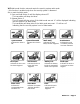
Door Lock Diagrams Follow the diagrams below for connecting basic door lock systems. For Two Stage door lock systems (separately unlocks driver and passenger doors) see following pages.
Two Stage Door Lock Diagrams The Astra 777 is equipped with a dedicated Passenger Unlock output allowing Two Stage Door Lock operation. When connected as shown below, disarming the system will unlock only the driver’s door. Pressing the disarm button again will unlock all doors.
Two Stage Door Lock Diagrams cont’d Two Stage Reverse Polarity Two Stage Adding Actuators Page 22 - Astra 777
Technical Information FCC ID: OARRXAM2000 This device complies with Part 15 of FCC Rules. Operation is subject to the following two conditions: 1) This device may not cause harmful interference.
Wiring Diagram ScyTek Electronics 11627 Cantara Street North Hollywood, CA 91605 www.scytek.