2000RS PLUS SERIES REMOTE START SYSTEM PRODUCT MANUAL
Limited Lifetime Warranty This vehicle remote start system is warranted to the original purchaser, to be free from defects in material and workmanship. The manufacturer will repair or replace at its option, and free of charge for the first twelve (12) months, any part that proves defective in material or workmanship under normal installation, use, and service, provided the product is returned to the manufacturer freight prepaid.
Table of Contents 1. 2. 3. 4. 5. 6. 7. 8. 9. 10. 11. 12. 13. 14. About Your System . . . . . . . . . . . . . . . . . . . . . . . . . . . . . . . . . . . . . . . . . . . . . . . . . . . .Page 1 Remote Transmitters . . . . . . . . . . . . . . . . . . . . . . . . . . . . . . . . . . . . . . . . . . . . . . . . . . .Page 2 Remote Transmitter Description . . . . . . . . . . . . . . . . . . . . . . . . . . . . . . . . . . . . . . .Page 2 Adding/Replacing Transmitters . . . . . . . . . . . . . . . . . . . .
About Your System The ScyTek Galaxy Starter is a started-of-the-art remote starting system featuring a built-in "ScyNet Network Port" that allows direct connection of optional accessory modules and a PC interface offering expanded system operation. With proper installation this system will provide superior protection and performance for many years to come.
Remote Transmitters Remote Transmitter Description LED Button 1 Button 2 Button 5 Button 3 Button 4 The Galaxy Starter is supplied with two 5-button Remote Transmitters used to control system operations. Note: Using the optional PC or Pocket PC interface with the network software, it is possible to reconfigure the functionality of the transmitter buttons. The standard (default) setting for operation of the transmitters is described below.
Adding/Replacing Transmitters To replace lost or stolen transmitters or to add additional transmitters into the system, have all desired transmitters ready and follow the steps below. Note: Up to 4 transmitters can be programmed to operate the system. To erase any previously stored transmitter codes, be sure to program all 4 transmitter memory locations. To program the transmitter(s): 1. Turn on the ignition key On, Off, On, Off, and back On. · The parking lights will flash 3 times. 2.
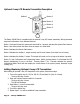
Optional 2-way LCD Remote Transmitter Description Button 1 Button 2 Button 3 Button 4 Button 5 The Galaxy 2000RS Plus is compatible with the optional 2-way LCD remote transmitter, offering increased range and confirmation of any activated features. Button 1 Locks and Unlocks the system and when held for 2 seconds, activates the system’s Panic feature. Button 1 also locks/unlocks the doors when the system is in Valet Mode. Button 2 Activates the Remote Start feature.
LCD Transmitter Battery Replacement Your Galaxy Remote Transmitter uses a 1.5 volt AAA alkaline battery, which will require replacement in time. Depending on the amount of use, the battery may last up to six months before it needs replacement. When the battery needs replacing, the system’s operating range will decrease, the LCD display will show only one of three bars in the battery icon, or the display and sounds may suddenly stop and start as the battery voltage drops below minimum.
System Operation Remote Locking To Lock the doors: 1. Turn off the ignition. 2. Press Button 1. · The audible status output will beep (if connected) · The doors will lock. · The parking lights will flash once. · The LED will turn on red, to indicate the doors are locked. 3. 10 seconds after Locking: · The LED will start blinking as a theft deterrent. Remote Unlocking To Unlock the doors: Press Button 1. · The audible status output will beep (if connected) · The doors will unlock.
Remote Start Features Remote Starting To Remote Start the System: 1. Be sure the system is not in Valet Mode. 2. Press and hold Button 4 for three seconds. · The parking lights will turn on. · The LED will flash rapidly. · The engine will start and run for the duration of its programmed Run Time.* · The heater or air conditioner will turn on (if turned on prior to exiting the vehicle). *If the engine fails to start on the first attempt, it will repeat the starting procedure 2 more times.
Automatic Start Mode The Automatic Start Mode allows the vehicle to automatically start the vehicle every one or two hours and run for the preset Run Time. To turn on Auto Cold Starting: 1. Turn Ignition switch Off and wait for 3 seconds. 2. Turn Ignition switch On and Off three times ending with Ignition in Off position 3. Press the Valet switch within three seconds Side lights will flash indicating that the Cold Start mode has been activated.
Extended Features Ignition Door Locking For added safety, the Ignition Door Locking feature allows vehicles equipped with power door lock systems to automatically lock the doors when the ignition is turned on. If a door is open when the ignition is turned on, the Ignition Door Locking feature is disabled to protect against locking the keys inside the vehicle. Ignition Door Unlocking For added convenience, this feature automatically unlocks the doors after the ignition key is turned off.
System Installation 1. 2. Thoroughly read and become familiar with the installation instructions before beginning the installation. Review system contents: Main Unit Two 5-Button Remote Transmitters Harnesses • 6-Pin starter harness • 20-Pin main harness • 4-Pin auxiliary start harness • 3-Pin door lock harness • LED harness • Override Switch harness 3. 4. Verify vehicle is equipped with electronic fuel injection, and starts/idles normally before installation.
System Wiring 6-Pin Starter Harness Pin 1 RED WIRE A: Main Power Input A (+). Connect to the battery or constant power wire at the ignition switch with a minimum 30 Amp supply. Remove fuse until installation is complete and wiring is checked. Pin 2 RED WIRE B: Main Power Input B (+). Connect to the battery or constant power wire at the ignition switch with a minimum 30 Amp supply.
Pin 13 WHITE/BLACK WIRE: Hood Pin Input (-). Connect the to the hood pin switch. The switch must provide a ground output when switch is opened. Pin 14 ORANGE WIRE: Starter Interrupt Output (-) 500 mA. The wire provides a ground output when doors are locked with remote control. Pin 15 VIOLET/WHITE WIRE: Factory Disarm Output (-) 500 mA. The Violet/white wire provides a ground output on disarming and before remote starting to disarm a factory security system.
Jumper Settings Jumper Selection Carefully separate the top and bottom halves of the main unit case. Once the cover is removed, the parking light polarity jumper will be visible next to the parking light relay. Set the jumper for the correct polarity output as described below, then reassembly the main unit case. Parking Light Output. Selects the polarity (+/-) for the output of the on-board Parking Light relay.
System Programming Entering System Programming Although this system is compatible with the optional FM transmitter, all programming is performed using the standard AM transmitter unless otherwise noted. To enter System Programming: 1. Turn on ignition. 2. Within 5 seconds, press the valet switch 5 times. · The parking lights will provide three blinks, indicating that you have entered Programming. 3. Press the valet switch the number times equal to the System Parameter you want to change.
Branch Feature Button 1 (default) Button 2 Button 3 1. Ignition Door Locking On Off 2. Ignition Door Unlocking Unlock All Unlock Driver Only Off 3. Door Unlock Pulse Single Double 4. Door Lock Pulse Length 1 second 3 seconds 5. Aux 2 Activate on Lock Off On 6. Aux 1 Mode Pulsed Timed Latched 7. Aux 2 Mode Pulsed Timed Latched 8. not used 9. Start in Valet Mode Disable Enabled 10. Lock after Start On Off 11. Lock after Shutdown On Off 12. Engine Run Time 15 minutes 25 minutes 13.
14. Engine Sense Mode. Selects between Tachless and Tach Monitor operation. Tachless. Determines the engine status using an advanced software routine, without requiring connection to the vehicle’s tachometer. Tachless operation may not be compatible with some vehicles or in severe temperatures, in which case the tach wire must be connected. Tach Monitor. Monitors the vehicle’s tach wire (or a fuel injection wire) in real-time to determine engine status and adjust starter crank time automatically.
Wiring Diagrams Positive Dome Negative Dome TO POSITIVE DOME LIGHT TO NEGATIVE DOME LIGHT Black/White (-) DOME LIGHT OUTPUT Black/White (-) DOME LIGHT OUTPUT +12V +12V Positive Horn Negative Horn TO POSITIVE HORN WIRE TO NEGATIVE HORN WIRE Brown/White (-) HORN OUTPUT Brown/White (-) HORN OUTPUT +12V +12V Negative Glow Plug Starter Anti-Grind +12V (-) GLOW PLUG WIRE FROM VEHICLE ON CK Violet Wire (+) STARTER ART ST Blue/Yellow Wire (+) GLOW PLUG INPUT Yellow Wire (+) IGNITION Orange w
Door Lock Diagrams Follow the diagrams below for connecting basic door lock systems. For Two Stage door lock systems (separately unlocks driver and passenger doors) see following pages.
Two Stage Door Lock Diagrams The Galaxy Starter is equipped with a dedicated Passenger Unlock output allowing Two Stage Door Lock operation. When connected as shown below, unlocking the system will unlock only the driver’s door. Pressing the unlock button again will unlock all doors.
Two Stage Door Lock Diagrams cont’d Two Stage Reverse Polarity Two Stage Adding Actuator Page 20 - Galaxy 2000RS Plus
Galaxy 2000RS Plus - Page 21
Page 22 - Galaxy 2000RS Plus
Technical Information FCC ID: OARRXAM2000 This device complies with Part 15 of FCC Rules. Operation is subject to the following two conditions: 1) This device may not cause harmful interference.
Wiring Diagram ScyTek Electronics 11627 Cantara Street Unit B North Hollywood, CA 91605 © ScyTek Electronics 2003 Galaxy Starter r5 2/18/04