
Manual

SECURITY DOOR CONTROLS
801 Avenida Acaso, Camarillo, Ca. 93012 • (805) 494-0622 • Fax: (805) 494-8861
www.sdcsecurity.com • E-mail: service@sdcsecurity.com
1591U EMLOCK
®
INSTALLATION INSTRUCTIONS
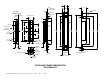
1. Prepare door jamb for EMLock per template drawing.
2. Locate reinforcement plate and mounting tabs as shown.
3. Center Armature Plate to the centerline of the lock. The cutout for the armature must be 1-1/2” wide
and 6-1/2” long.
4. Install an armature reinforcement plate or the Amp mounting plate so that there is a 5/8” pocket when
measured from the leading edge of the door. The AMP mounting plate is used to reinforce the mortise
cutout in a wood door. It is secured to the door with four (4) #10 wood screws and then the EMLock
armature is secured to the mounting plate with a 5/16”-18 x 3/4” bolt.
NOTE: The AMP mounting plate is an option available from SDC.
5. Attach the EMLock wire leads to the power source and then install the EMLock and the armature with
screws provided.
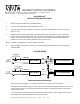
SYSTEM WIRING
ELECTRONICS
24V CONFIGURATION
BLK
RED
ORG
WHT
(+) RED/BLK
TO 24 VDC
FUSED
POWER SOURCE
(-) WHT/BLK
RED
RED
ACCESS, EGRESS
AND
REMOTE CONTROLS
+
-
ELECTRONICS
12V CONFIGURATION
BLK
RED
ORG
WHT
(+) RED/BLK
(-) WHT/BLK
RED
RED
ACCESS, EGRESS
AND
REMOTE CONTROLS
TO 12 VDC
FUSED
POWER SOURCE
+
-
IMPORTANT WIRING INFORMATION:
Use the system wiring diagram to configure the EMLock for 12 VDC or 24 VDC operation.
Although using a DC power supply is recommended, a transformer with a bridge rectifier may also be used
as a DC power source. If you are using a transformer and rectifier, a transformer with the correct output
voltage must be used.
Access controls must not be wired to the AC side of the bridge rectifier or power supply. Access controls
must always be wired to break the DC side of the power source.
P:\INSTALLATION INST\Electromagnetic Locks\INST-1591U.vsd REV A 06-11 Page 1