801 Avenida Acaso, Camarillo, Ca. 93012 • (805) 494-0622 • www.sdcsecurity.com E-mail: service@sdcsecurity.com S6100 SERIES REVERSIBLE PANIC/FIRE EXIT RIM DEVICES INSTALLATION INSTRUCTIONS These instructions are presented a in step by step sequence. Please read it through before installation. Note: The dimensions of the Template are shown in inches. See attached page for the Metric Conversion Table for millimeters. P:\INSTALLATION INST\Mechanical Hardware\INST-S6100.
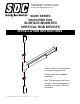
End Cap Bracket A. DESIGNATION OF PARTS Chassis End Cap Dogging Device (Fire Exit Hardware is not Equipped with this device) Chassis Push Bar Chassis Cover Strike Latch Assembly B. TYPE OF INSTALLATION A. Single Door B. Double Door with Mullion TRIM DOOR TRIM C. Double Door without Mullion TRIM DOOR TRIM DOOR DOOR DOOR DOUBLE DOOR STRIKE MULLION 2-7/16” 2-7/16” CL 2-7/16” CL CL C. MARK POSITION FOR INSTALLING 1.
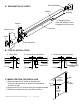
STOP LINE Jamb D. INSTALL STRIKE TO FRAME 1. Place strike over the drilled holes, and attach it to the jamb or mullion with the supplied screws. 2. If installing with a vertical rod device for double doors, and additional Double Door Strike must be used in place of the regular strike provided. Door CL of Device Strike Site Strike E. IF CYLINDER IS INCLUDED WITH THE DEVICE 1. Drill one 1-3/16" diameter thru hole for the cylinder/bracket plate. 2. Insert cylinder and cylinder collar from outside of door.
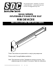
Mark mounting holes through End Cap Bracket after device is level A NOTE: The Device bar has 3 different lengths; Standard 3' Door Device = Approx 33" Standard 3.5' Door Device = Approx 40" Standard 4' Door Device = Approx 44" Latch Assembly The bar lengths of devices are pre-cut for 36", 42" and 48" wide door, no additional cutting is necessary. If narrower door installation is needed, cut device at the “A” location, to door width minus 4" to fit properly. H. INSTALL COVERS 1.
801 Avenida Acaso, Camarillo, Ca. 93012 • (805) 494-0622 • www.sdcsecurity.com E-mail: service@sdcsecurity.com S6200 SERIES PANIC/FIRE EXIT SURFACE MOUNTED VERTICAL ROD DEVICES INSTALLATION INSTRUCTIONS These instructions are presented in a step by step sequence. Please read it through before installation. Note: The dimensions are shown in inches. See attached page for the Metric Conversion Table for millimeters. P:\INSTALLATION INST\Mechanical Hardware\INST-S6200.
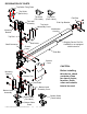
DESIGNATION OF PARTS Top Strike Fixing Plate Top Strike (Back View) Mounting Bracket Top Strike Top Strike (Panic Label) (Fire Label) Top Latch End Cap Bracket Assembly Top Latch Assembly Cover Mechanism Housing End Cap Top Rod Dogging Device Fire Exit Hardware is not equipped with this device Rod Guide Shaft Connector Chassis Assy.
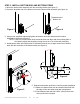
STEP 1: PREPARE DOOR 1. Mark position of holes on the door per template (see figure 1). 2. Drill all holes marked on the door for the device chassis and top and bottom latch mounting brackets. 3. Mortise hole for outside trim is required. NOTE; Any hole drilled from the outside, first needs a pilot hole drilled from the inside to ensure good alignment. Mark Backset 2-7/16” JAMB 2-5/16" Prepare door for your specific device per supplied template.
STEP 2: INSTALL BRACKETS, DEVICE & TRIM 1. Remove chassis cover from chassis assembly and end cap from end cap bracket. 2. Cut the length if required. For user information; This model device has three different lengths: For use on 3' wide door, device = 33" For use on 3.5' wide door, device = 40" For use on 4' wide door, device = 44" a. The device length is pre-cut for use on 36", 42" or 48" wide doors, no additional cutting is necessary.
STEP 3: INSTALL BOTTOM ROD AND BOTTOM STRIKE 1. Mount the bottom latch assembly into the mounting bracket (see figure 3). 2. Screw the threaded end of the bottom rod onto the bottom latch assembly (see figure 4). Threaded end of Bottom rod Figure 3 Figure 4 3. Using screw supplied, attach and tighten the bottom rod to the chassis at the location indicated by the arrow in figure 5.
STEP 4: INSTALL TOP ROD AND TOP STRIKE 1. Mount the top latch assembly into the mounting bracket (see figure 7). 2. Screw the threaded end of the top rod onto the top latch assembly completely (see figure 8). Threaded end of top rod Figure 7 Figure 8 3. Measure and cut the length of the top rod. The length of the top rod is measured to the edge of the rod connector (see figure 9) which will be attached to the chassis. 4.
6. Mark and drill mounting holes on the jamb for the top strike per the strike template (see figure 12). Fasten the top strike to the jamb with the screws supplied (see figure 13). Figure 12 Figure 13 NOTE: Attach third screw last after strike has been properly aligned, STEP 5: TEST OPERATION 1. Depress the push bar. The top and bottom latches should be held retracted. The bottom latch should also clear the floor and the bottom strike. Door can now be opened. 2.
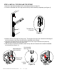
Outside of Door Door Handing Use this diagram to determine the hand of door. RHR LHR Inside of Door NOTE: To extend the life of this device, it is recommended to activate the dogging feature during high traffic periods of the day. Dogging Wrench Dogging: Release Dogging: Insert dogging wrench and turn clockwise 15 degrees. Insert dogging wrench and turn counter-clockwise 15 degrees. Depress Push Bar Depress Push Bar The push bar will remain pressed and the latches will remain retracted.
801 Avenida Acaso, Camarillo, Ca. 93012 • (805) 494-0622 • www.sdcsecurity.com E-mail: service@sdcsecurity.com S6800 SERIES PANIC/FIRE EXIT CONCEALED VERTICAL ROD DEVICES INSTALLATION INSTRUCTIONS These instructions are presented in a step by step sequence. Please read it through before installation. Note: The dimensions of the Template are shown in inches. See attached page for the Metric Conversion Table for millimeters. P:\INSTALLATION INST\Mechanical Hardware\INST-S6800.
DESIGNATION OF PARTS Rod Length Locator Top Strike Fixing Plate Top Strike (Back View) Top Strike (Fire Label) Top Strike (Panic Label) End Cap Latch Mounting Plate End Cap Bracket Mechanism Housing Top Latch Assembly Top Rod Dogging Device Fire Exit Hardware is not equipped with this device Shaft Connector Push Bar Latch Actuated Shaft Chassis Cover Before installing this device, check contents of box for size of device, function, finish color and outside trim to be used.
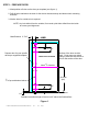
CL of Device A. PREPARE DOOR 1. Mark centerline of device by drawing a line across the door. 2-7/16" Figure 1-1 2. Mark a backset line and 4 thru holes for device chassis shown on the template provided. Mark backset from edge of door INSIDE FACE OF DOOR 3. Prepare the door cut-outs by using the template provided. Drill holes and cut-outs on the Device side ONLY 39 4” -3/ CL of Device The centerline of the device must be 40" above the finished floor. Bottom Door gap MUST be 1/4”.
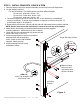
B. ASSEMBLE RODS AND LATCHES 1. Screw bottom rod into bottom latch assembly (figure 2-1). 2. Assemble top rod: 2-1 Connect short top rod to long top rod using rod connector (figure 2-1). 2-2 Measure and cut the length of the top rod if it is too long. Bottom rod Bottom latch assembly Figure 2-1 Figure 2-2 2-3 Insert shaft connector into the non-threaded end of the top rod and tighten screw to fix in place (figure 2-3). 3. Screw top rod assembly into top latch assembly (figure 2-4).
C. MOUNT LATCH ASSEMBLIES 1. Attach latch mounting brackets to top and bottom latch assemblies 2. Insert top latch assembly into top of the door and fasten to the mounting plates with the screws provided (figure 3-1). 3. Insert bottom latch assembly into bottom of the door and fasten to the mounting plates with the screws provided (figure 3-2).
3. Adjustment procedure: Adjust the length of the two vertical rods by hand through the cut-outs (figure 4-2). Shorten or lengthen the rods by turning into or out of the latch assemblies (figure 4-3) until the holes of the shaft connectors are in the proper position as determined by the latch length locator (pg. 5, figure 4-1). Figure 4-2 Figure 4-3 E. INSTALL LATCH ACTUATOR SHAFTS 1. Attach one Latch Actuated Shaft to the top and bottom shaft connectors (figure 5) with screws supplied. 2.
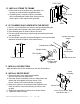
3. Cut the length if required: a. The device length is pre-cut for use on 36", 42" or 48" wide doors, no additional cutting is necessary. If narrow door installation is required, cut device at section “A” to door width minus 2" for proper fit. b. Remove device from door, remove end cap and end cap bracket and cut where required. NOTE: Device must be cut flat with all burrs removed for end cap to fit properly. 4. Mount device horizontally via the drilled holes and secure with supplied mounting hardware.
2. Release push bar, Make sure both top and bottom latch bolts are FULLY extended 3. Check top latch bolt for deadlocking function. Deadlock Depress the deadlock plate by hand. Top Latch Plate When the deadlock plate is depressed, Bolt the latch bolts should be locked in the Figure 7-3 extended position and unable to be pressed down (figure 7-3). 4. Check device operation by depressing and releasing push bar several times to assure correct final installation. 5.
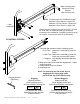
I. INSTALL BOTTOM STRIKE 1. Bore the hole into the finished floor or threshold (figure 9-1). 2. Install bottom strike into the hole (figure 9-2). CL of Bottom Latch 2.441" 1.126" DOOR (Top View) CL of Bottom Latch .748" DIAMETER 1.850" 1/4” 1/4” NOTE: For flat thresholds the clearance must be provided in sill to accommodate full 9/16" (15mm) throw of latch bolt. Flat threshold application (Panic device ONLY) Strike application J. INSTALL COVERS 1.
Outside of Door Door Handing Use this diagram to determine the hand of door. RHR LHR Inside of Door NOTE: To extend the life of this device, it is recommended to activate the dogging feature during high traffic periods of the day. Dogging Wrench Dogging: Release Dogging: Insert dogging wrench and turn clockwise 15 degrees. Insert dogging wrench and turn counter-clockwise 15 degrees. Depress Push Bar Depress Push Bar The push bar will remain pressed and the latches will remain retracted.
801 Avenida Acaso, Camarillo, Ca. 93012 • (805) 494-0622 • www.sdcsecurity.com • E-mail: service@sdcsecurity.com INSTALLATION INSTRUCTIONS S6000-ATS ANTI-TAMPER SWITCH KIT Insert Anti-Tamper Switch where shown. Remove Device Cover and End Cap. END CAP BRACKET DEVICE COVER END CAP Insert the S6000-ATS Assy. into the device. Slide the End Cap over the End Cap Bracket. Position the S6000-ATS Assy so the switch arm makes contact and is activated by the inside surface of the End Cap.