
User guide


IV. Applications (Continued)
Section IX – Single Relay Control Mode – Go To Pages 14 & 15
In Single Relay Control Mode, the UR2-4 operates as four (4) individually controlled relays.
Stations A1 & B1 each provide:
(1) Fused, SPDT lock output, wet or dry and
(1) Dry trigger input
Stations A2 & B2 each provide:
(1) Non-fused, SPDT lock output, wet or dry and
(1) Dry trigger input
Each input may be individually configured to operate as a conventional relay or a time delayed relay.
Alternatively, each input may be individually configured to operate as a latching relay or a time delayed relay.
As a conventional relay (CR), the lock output relay is only activated while the trigger input is activated. Once the trigger input is
released, the output relay returns to its resting state.
As a time delayed relay (TD), the lock output relay is activated by the trigger input. Once the trigger input is released, the output
remains activated for a specified period of time, as configured by the dip switches.
As a latching relay (LR), the lock output relay is activated by the trigger Input. A single activation and release of the latching trigger
input latches the lock output relay. The lock output relay remains latched until the latching trigger input is reactivated.
Section X – 2-Door Communicating (Shared) Bath System – Go to Page 16 & 17
Both doors are normally closed and unlocked.
System Activation:
Upon entering the bathroom and closing both doors, pressing an Activation button will lock both doors, and turn on the indicator
lamps on the Activation and Emergency Unlock buttons, indicating the bathroom is occupied.
System Deactivation:
When using EMLocks®, pressing the Activation button a second time will unlock both doors and turn off all indicator lamps.
When using fail-safe electric strikes or electrified locksets, operating the inside lever to retract the latch on either door will unlock both
doors and turn off all indicator lamps. Using a key override from the outside to enter either door will also reset the system and unlock
both doors.
Emergency Override:
Emergency Unlock buttons located outside each bathroom door will immediately unlock its specified door and indicate its activation
by causing the button’s indicator lamp to flash. Pressing the Emergency Unlock button a second time will return the door to the
locked state and the indicator lamp will return to a steady lighted state. Pressing the Activation button during an emergency override,
will reset the system and unlock both doors.
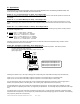
Activating a single input will trigger a single output:
Station A, Input 1 controls Output 1
Station A, Input 2 controls Output 2
Station B, Input 1 controls Output 3
Station B, Input 2 controls Output 4
FAIL-
SECURE
LOCK
FAIL-
SAFE
LOCK
-
+
-
+
FAIL-
SECURE
LOCK
FAIL-
SAFE
LOCK
-
+
-
+
P:\INSTALLATION INST\Power Supplies\INST-UR\INST-UR2-4.vsd REV 12-11 Page 4
+
(-)
W
D
W
D
FUSE
W
D
W
D
FUSE
(
-
)
N
O
N
C
C
(
-
)
N
O
N
C
C
(
-
)
N
O
N
C
C
(
-
)
N
O
N
C
C
OUTPUT 2
OUTPUT 4
OUTPUT 1 OUTPUT 3
POWER
}
}
Input
1
Input
2
C A1 C A2 C B1 C B2
Station A
Station B
}
}
Input
1
Input
2
X. 2-Door Communicating Bath System
Setup
Follow the installation steps below before applying power to the UR2-4.
Refer to the 2-Door Communicating Bath System wiring diagram on
Page 16.
It is assumed that the UR2-4 and locks will share the same power supply.
Step 1 – Set Dip Switches
The dip switch settings for a 2-Door Communicating Bath System must be
set as shown below.
Step 2 – Configure the Relay Outputs to be Wet
(Voltage) or Dry.
Use the red WET/DRY Selection Jumpers to configure each output.
Refer to Page 2 of this instruction for selection procedure.
For a 2-Door Communicating Bath System, all outputs (1 through 4) are
configured as wet outputs.
The relay output voltage will be the same as the UR2-4 input voltage (12
or 24VDC).
Step 3. Terminate the Activation and Emergency
Unlock Buttons
Connect the (2) Emergency Unlock buttons and (1) Activation button as
shown on the Communicating Bath system wiring diagram.
NOTE: Each Emergency Unlock button will only unlock its corresponding
door.
All button switches are wired Normally Open.
Lamp voltage is not polarity sensitive.
NOTE: All low voltage wiring shall be 18-gauge minimum. The minimum
lock power wire gauge shall be determined by the SDC wire gauge chart.
Signal wire shall be 22-guage minimum.
Step 4. Terminate the Lock Power and Lock
Monitoring Options
Select your specific lock type below. Follow the typical Communicating
Bath system wiring diagram. Be careful to observe lock voltage polarity.
NOTE: All lock monitoring options below (LBM, DPS, and/or REX) are to
be wired OPEN when the doors are CLOSED and LATCHED.
Using EMLocks®:
Using Fail-safe Uni-FLEX™ Electric Strikes:
Using Fail-safe Selectric® Pro Locks:
Step 6. Connect a 12 or 24VDC Power Source to the
UR2-4 Controller.
Before applying power, verify that all the connections are securely
terminated by gently pulling on each wire.
Terminate the voltage wiring to the Controller Power Input. Be careful to
observe polarity.
Verify that both doors are closed & apply power to the controller.
Step 7. UR2-4 Controller Startup and Operation
Verification.
Verify the polarity of the inputs by observing the Status Lights located on
the lower right of the controller.
With the system at rest, Status Lights A1, A2, B1, B2, & E1 should all be
turned off.
Test the standard operation of the Communicating Bath System as
described on Page 4.
SW1 -1 = OFF
SW1 -2 = OFF
SW1 -3 = OFF
SW1 -4 = OFF
SW1 -5 = OFF
SW1 -6 = OFF
SW1 -7 = OFF
SW1 -8 = ON This switch must be set ON fo r Co mm. B ath M o de
SW2-1 = OFF
SW2-2 = OFF
SW2-3 = OFF
SW2-4 = OFF
SW2-5 = OFF
SW2-6 = OFF
SW2-7 = OFF
SW2-8 = ON
Switches the UR bo ard between Interlo ck M o de or Co ntrol
M ode. This switch must be set ON for Co mm. B ath M o de
P:\INSTALLATION INST\Power Supplies\INST-UR\INST-UR2-4.vsd REV 12-11 Page 17
EMLock® with DPS
(12 OR 24 VDC)
3 4 5 6 7 8
NC
C
NO
DPS
LOCK
PWR
To Lock
Monitoring
Input
LBM
Fail-safe Electric Strike
w/ Latch Bolt Monitoring (LBM)
NOTE: Mechanical locksets are
configured for “Storeroom”
function.
NO
+
-
LOCK
PWR
To Lock
Monitoring
Input
NC
C
Fail-safe Electrified Mortise Lock
w/ Door Position Switch (DPS) &
Request-to-Exit Switch (REX)
C
NO
+
-
NC
C
NO
NC
DPS
REX
To Lock
Monitoring
Input
LOCK
PWR