
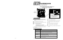
User guide

+
(-)
1 2
3 4 5 6 7 8
1 2
3 4 5 6 7 8
SW1
SW2
W
D
W
D
FUSE
W
D
W
D
FUSE
UR2-4
(
-
)
N
O
N
C
C
(
-
)
N
O
N
C
C
(
-
)
N
O
N
C
C
(
-
)
N
O
N
C
C
POWER
OUTPUT 2
OUTPUT 4
OUTPUT 1
OUTPUT 3
C A1 C A2 C B1 C B2
C E1 C E2 C E3 C E4
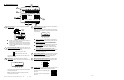
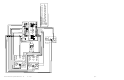
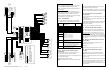
III. UR2-4 Board Layout
1
P:\INSTALLATION INST\Power Supplies\INST-UR\INST-UR2-4.vsd REV 12-11 Page 2
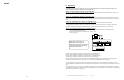
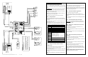
RELAY OUTPUTS – The UR2-4 provides four (4) individual
SPDT relay outputs.
Outputs 1 & 3 are fused. These outputs are typically used
to power the door locking hardware.
Outputs 2 & 4 are non-fused. These outputs are typically
used as auxiliary (monitoring) relays. They may be used
to power a remote status annunciator, or send a signal to
a security panel.
WET/DRY SELECTION JUMPER – Each relay output may be
individually configured as a wet (voltage) or dry output. Use the
supplied jumpers to configure each relay.
Jumper over top 2 pins = WET
Jumper over bottom 2 pins = DRY
The relay output voltage will be the same as the UR2-4 input
voltage (12 or 24 VDC).
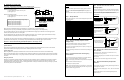
MAIN INPUTS – The UR2-4 provides four (4) individual
optically isolated inputs. The inputs must be connected to a dry
switch.
These inputs may be collectively configured as Normally Open
or Normally Closed inputs.
NOTE: If Normally Closed inputs are selected, all unused
inputs will need to be shorted.
1
2
W
D
W
D
3
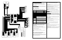
AUXILIARY INPUTS – The UR2-4 provides four (4) individual dry,
optically isolated auxiliary inputs.
NOTE: These input connections are optional and must be wired
as Normally Open connections. The input will only be active when
closed (shorted).
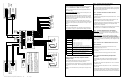
Input E1 – LOCK ALL – When activated, this input will lock
all the doors, until the input is deactivated. Main Inputs will
be ignored.
Input E2 – UNLOCK ALL – When activated, this input will
unlock all the doors, until the input is deactivated. Main
Inputs will be ignored.
Input E3– LOCKOUT – When activated, this input will cause
all the lock outputs to remain in their current state, and
ignore changes to the Main Inputs. Lock/Unlock All inputs
will also ignored.
Input E4 – EMERGENCY RELEASE (FIRE ALARM) –
When activated, this input will simultaneously release all fail-
safe locks. Main Inputs, Lock/Unlock All inputs, and the
Lockout input will be ignored.
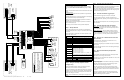
INPUT POWER CONNECTION – The UR2-4 must be powered by
a filtered and regulated 12 or 24VDC Power Supply. SDC 600
Series Power Supplies are designed to accommodate and
interface with up to two (2) UR2-4 controllers.
MODE CONFIGURATION DIP SWITCHES – The UR2-4 utilizes
two (2) 8-position dip switch modules for configuring the system
operational modes. They are SW1 and SW2.
STATUS LIGHTS – The UR2-4 provides diagnostic lights to show
the status of each individual input and output on the board.
If an output is active, its corresponding light
will be ON.
If an input is closed, its corresponding light
will be ON.
4
5
6
O
1
O
2
O
3
O
4
A
1
A
2
B
1
B
2
E
1
E
2
E
3
E
4
7
Station A Station B Auxiliary Inputs
2
3
4
C E1 C E2 C E3 C E4
}
}
Input
E1
Input
E2
}
}
Input
E3
Input
E4
W
D
W
D
FUSE
OUTPUT 2OUTPUT 1
(
-
)
N
O
N
C
C
(
-
)
N
O
N
C
C
FAIL-
SECURE
LOCK
FAIL-
SAFE
LOCK
-
+
-
+
Monitoring
Relay
Output
+
(-)
POWER
C A1 C A2 C B1 C B2
}
}
Input
A1
Input
A2
}
}
Input
B1
Input
B2
Station A Station B
1 2 3 4 5 6
7 8
1 2 3 45 6
7 8
SW1
SW2
ON
ON
5
6
7
IN
OUT
Page 19