
User guide


IV. Applications
For detailed wiring instructions and setup, select your specific application from the following available modes, and
continue to the page number indicated next to the section title.
Section V – 2, 3, or 4-Door Interlock “A” Setup - Go To Pages 5 & 6
All doors are normally closed and unlocked. Opening any door causes the other doors to lock until the opened door returns to its
normal state.
Section VI – 2, 3, or 4-Door Mantrap “B” Setup – Go To Pages 7 & 8
All doors are normally closed and locked. Each door may be individually unlocked using the Access Control System or a remote
release. Unlocking any door causes the other doors to be incapable of being unlocked until the unlocked door returns to its normal
state.
Section VII – 2, 3, or 4-Door Interlock “C” Setup – Go To Pages 9 & 10
All doors are normally closed. Up to three (3) doors may be normally locked, and the remaining door(s) will be normally unlocked.
The possible configurations are:
2 Doors: Door 1 – Locked, Door 2 – Unlocked
3 Doors: Door 1 – Locked, Doors 2 & 3 – Unlocked
Doors 1 & 2 – Locked, Door 3 – Unlocked
4 Doors: Door 1 – Locked, Doors 2, 3, & 4 – Unlocked
Doors 1 & 2 – Locked, Doors 3 & 4 – Unlocked
Doors 1, 2, & 3 – Locked, Door 4 – Unlocked
Unlocking or opening any door will lock the unlocked doors, and make the locked doors incapable of being unlocked, until the
unlocked/opened door returns to its normal state.
Section VIII – Dual Relay Control Mode – Go To Pages 11 & 12
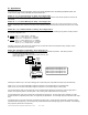
In Dual Relay Control Mode, the UR4-8 operates as four (4) individually controlled relay stations. Each station provides:
(1) Fused, SPDT lock output, wet or dry,
(1) Non-fused, SPDT auxiliary (monitoring) output, wet or dry, and
(2) Dry trigger inputs
Activating each station’s Input 1 OR Input 2 will trigger the corresponding lock output AND the auxiliary output simultaneously.
Inputs A1, B1, C1, & D1 may be individually configured to operate as a conventional relay or a time delayed relay.
Inputs A2, B2, C2, & D2 may be individually configured to operate as a conventional relay or a latching relay.
As a conventional relay (CR), the lock output relay is only activated while the trigger input is activated. Once the trigger input is
released, the output relay returns to its resting state. The monitoring relay output follows the lock output relay.
As a time delayed relay (TD), the lock output relay is activated by the trigger input. Once the trigger input is released, the output
remains activated for a specified period of time, as configured by the dip switches. The monitoring relay output follows the lock output
relay.
As a latching relay (LR), the lock output relay is activated by the trigger Input. A single activation and release of the latching trigger
input latches the lock output relay. The lock output relay remains latched until the latching trigger input is reactivated. The monitoring
relay output relay follows the lock output relay.
W
D
W
D
FUSE
OUTPUT 2
OUTPUT 1
(
-
)
N
O
N
C
C
(
-
)
N
O
N
C
C
FAIL-
SECURE
LOCK
FAIL-
SAFE
LOCK
-
+
-
+
Monitoring
Relay
Output
C A1 C A2 C B1 C B2
}
}
Input
1
Input
2
Station A
Station A Inputs control Outputs 1 & 2
Station B Inputs control Outputs 3 & 4
Station C Inputs control Outputs 5 & 6
Station D Inputs control Outputs 7 & 8
P:\INSTALLATION INST\Power Supplies\INST-UR\INST-UR4-8.vsd REV 03-11 Page 3