
User guide


IV. Applications (Continued)
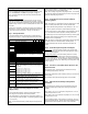
Section IX – Single Relay Control Mode – Go To Pages 13 & 14
In Single Relay Control Mode, the UR4-8 operates as eight (8) individually controlled relay stations.
Stations A1, B1, C1, & D1 each provide:
(1) Fused, SPDT lock output, wet or dry and
(1) Dry trigger input
Stations A2, B2, C2, & D2 each provide:
(1) Non-fused, SPDT lock output, wet or dry and
(1) Dry trigger input
Each input may be individually configured to operate as a conventional relay or a time delayed relay.
Alternatively, each input may be individually configured to operate as a latching relay or a time delayed relay.
As a conventional relay (CR), the lock output relay is only activated while the trigger input is activated. Once the trigger input is
released, the output relay returns to its resting state.
As a time delayed relay (TD), the lock output relay is activated by the trigger input. Once the trigger input is released, the output
remains activated for a specified period of time, as configured by the dip switches.
As a latching relay (LR), the lock output relay is activated by the trigger Input. A single activation and release of the latching trigger
input latches the lock output relay. The lock output relay remains latched until the latching trigger input is reactivated.
Section X – 2-Door Communicating (Shared) Bath System (Single or Dual) – Go to Page 15 & 16
Both doors are normally closed and unlocked.
System Activation:
Upon entering the bathroom and closing both doors, pressing an Activation button will lock both doors and turn on the indicator lamps
on the Activation button and Emergency Unlock buttons, indicating the bathroom is occupied.
System Deactivation:
When using EMLocks®, pressing the Activation button a second time will unlock both doors and turn off all indicator lamps.
When using fail-safe electric strikes or electrified locksets, operating the inside lever to retract the latch on either door will unlock both
doors and turn off all indicator lamps. Using a key override from the outside to enter either door will also reset the system and unlock
both doors.
Emergency Override:
Emergency Unlock buttons located outside each bathroom door will immediately unlock its specified door and indicate its activation
by causing the button’s indicator lamp to flash. Pressing the Emergency Unlock button a second time will return the door to the
locked state and the indicator lamp will return to a steady lighted state. Pressing the Activation button during an emergency override,
will reset the system and unlock both doors
C A1 C A2 C B1 C B2
}
}
Input
1
Input
2
Station A
Station A, Input 1 controls Output 1
Station A, Input 2 controls Output 2
Station B, Input 1 controls Output 3
Station B, Input 2 controls Output 4
Station C, Input 1 controls Output 5
Station C, Input 2 controls Output 6
Station D, Input 1 controls Output 7
Station D, Input 2 controls Output 8
W
D
W
D
FUSE
OUTPUT 2
OUTPUT 1
(
-
)
N
O
N
C
C
(
-
)
N
O
N
C
C
FAIL-
SECURE
LOCK
FAIL-
SAFE
LOCK
-
+
-
+
FAIL-
SECURE
LOCK
FAIL-
SAFE
LOCK
-
+
-
+
}
}
Input
1
Input
2
Station B
P:\INSTALLATION INST\Power Supplies\INST-UR\INST-UR4-8.vsd REV 03-11 Page 4