
User guide


DOOR
MONITORING
(DPS)
DOOR #1
DOOR #2
DOOR
MONITORING
(DPS)
DOOR
MONITORING
(DPS)
DOOR #3 DOOR #4
DOOR
MONITORING
(DPS )
LOCK
ALL
(Optional)
UNLOCK
ALL
(Optional)
EMERGENCY
RELEASE
(Optional)
Monitoring
Relay
Output
(Optional)
12/24 VDC
POWER
SUPPLY
SDC 600
Series
+
-
+
(-)
1 2 3 4 5 6
7 8
1 2
3 4 5 6 7 8
SW1
SW2
(
-
)
N
O
N
C
C
(
-
)
N
O
N
C
C
(
-
)
N
O
N
C
C
(-)
N
O
N
C
C
W
D
W
D
FUSE
W
D
W
D
FUSE
W
D
W
D
FUSE
W
D
W
D
FUSE
INTERLOCK “A” MODE
(
-
)
N
O
N
C
C
(
-
)
N
O
N
C
C
(
-
)
N
O
N
C
C
(
-
)
N
O
N
C
C
Power Input
12/24 VDC
FAIL-SECURE
LOCK
(12 OR 24 VDC)
FAIL-SAFE LOCK
(12 OR 24 VDC)
+
+
-
-
DOOR
#1
LOCK
FAIL-SECURE
LOCK
(12 OR 24 VDC)
FAIL-SAFE LOCK
(12 OR 24 VDC)
+
+
-
-
DOOR
#2
LOCK
OUTPUT 2
OUTPUT 4
OUTPUT 6 OUTPUT 8
OUTPUT 1
OUTPUT 3
C A1 C A2 C B1 C B2 C C1 C C2 C D1 C D2 C E1 C E2 C E3 C E4
LOCKOUT
(Optional)
FAIL-SECURE
LOCK
(12 OR 24 VDC)
FAIL-SAFE LOCK
(12 OR 24 VDC)
+
-
DOOR
#4
LOCK
FAIL-SECURE
LOCK
(12 OR 24 VDC)
FAIL-SAFE LOCK
(12 OR 24 VDC)
+
+
-
-
DOOR
#3
LOCK
+
-
OUTPUT 7OUTPUT 5
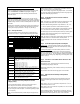
INSTALLATION NOTES:
1. Door Monitoring circuits have been configured to be
OPEN when the door is closed.
2. All Lock Relay Outputs (1, 3, 5, & 7) have been
configured to have wet (voltage) outputs. Lock output
voltage will be the same as the UR4-8 input voltage.
4. Monitoring Relay Outputs have been configured to
follow the Door Monitoring Input.
P:\INSTALLATION INST\Power Supplies\INST-UR\INST-UR4-8.vsd REV 03-11 Page 6
Monitoring
Relay
Output
(Optional)
Monitoring
Relay
Output
(Optional)
Monitoring
Relay
Output
(Optional)