
User guide


X. 2-Door Communicating Bath System
Setup (Single or Dual)
Follow the installation steps below before applying power to the UR4-8.
Refer to the 2-Door Communicating Bath System wiring diagram on
Page 16.
It is assumed that the UR4-8 and locks will share the same power supply.
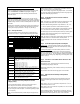
Step 1 – Set Dip Switches
The dip switch settings for a 2-Door Communicating Bath System must be
set as shown below.
Step 2 – Configure the Relay Outputs to be Wet
(Voltage) or Dry.
Use the red WET/DRY Selection Jumpers to configure each output.
Refer to Page 2 of this instruction for selection procedure.
For a Single Communicating Bath System:
Outputs 1, 2, 3, & 4 are configured to be wet outputs.
Outputs 5, 6, 7, & 8 are configured as dry outputs.
For Dual Communicating Bath Systems:
All outputs are configured to be wet outputs.
The relay output voltage will be the same as the UR4-8 input voltage (12
or 24 VDC).
Step 3. Terminate the Activation and Emergency
Unlock Buttons
For each system, connect the (2) Emergency Unlock buttons and (1)
Activation button as shown on the Communicating Bath system wiring
diagram.
All button switches are wired Normally Open.
Lamp voltage is not polarity sensitive.
NOTE: All low voltage wiring shall be 18-gauge minimum. The minimum
lock power wire gauge shall be determined by the SDC wire gauge chart.
Signal wire shall be 22-guage minimum.
Step 4. Terminate the Lock Power and Lock
Monitoring Options
Select your specific lock type below. Follow the typical Communicating
Bath system wiring diagram. Be careful to observe lock voltage polarity.
NOTE: All lock monitoring options below (LBM, DPS, and/or REX) are to
be wired OPEN when the doors are CLOSED and LATCHED.
Using EMLocks®:
Using Fail-safe Uni-FLEX™ Electric Strikes:
Using Fail-safe Selectric® Pro Locks:
Step 6. Connect a 12 or 24VDC Power Source to the
UR4-8 Controller.
Before applying power, verify that all the connections are securely
terminated by gently pulling on each wire.
Terminate the voltage wiring to the Controller Power Input. Be careful to
observe polarity.
Verify that both doors are closed & apply power to the controller.
Step 7. UR4-8 Controller Startup and Operation
Verification.
Verify the polarity of the inputs by observing the Status Lights located on
the lower right of the controller.
With the system at rest, Status Lights A1, A2, B1, B2, & C1 should all be
turned off.
Test the standard operation of the Communicating Bath System as
described on Page 4.
SW1 -1 = OFF
SW1 -2 = OFF
SW1 -3 = OFF
SW1 -4 = OFF
SW1 -5 = OFF
SW1 -6 = OFF
SW1 -7 = OFF
{OFF = Single Co mm Bath System;
ON = Dual Co mm Bath System}
SW1 -8 = ON This switch must be set ON fo r Co mm. Bath M ode
SW2-1 = OFF
SW2-2 = OFF
SW2-3 = OFF
SW2-4 = OFF
SW2-5 = OFF
SW2-6 = OFF
SW2-7 = OFF
SW2-8 = ON
Switches the UR board between Interlo ck M ode or Co ntrol
M ode. This switch must be set ON fo r Co mm. B ath M ode
P:\INSTALLATION INST\Power Supplies\INST-UR\INST-UR4-8.vsd REV 03-11 Page 15
EMLock® with DPS
(12 OR 24 VDC)
3 4 5 6 7 8
NC
C
NO
DPS
LOCK
PWR
To Lock
Monitoring
Input
LBM
Fail-safe Electric Strike
w/ Latch Bolt Monitoring (LBM)
NOTE: Mechanical locksets are
configured for “Storeroom”
function.
NO
+
-
LOCK
PWR
To Lock
Monitoring
Input
NC
C
Fail-safe Electrified Mortise Lock
w/ Door Position Switch (DPS) &
Request-to-Exit Switch (REX)
C
NO
+
-
NC
C
NO
NC
DPS
REX
To Lock
Monitoring
Input
LOCK
PWR