
User guide

P:\INSTALLATION INST\Power Supplies\INST-UR\INST-UR2-4.vsd REV 12-11 Page 12
LOCK
ALL
(Optional)
UNLOCK
ALL
(Optional)
EMERGENCY
RELEASE
(Optional)
LOCKOUT
(Optional)
INPUT 1
INPUT 2
Station A Triggers Station B Triggers
FAIL-SECURE
LOCK
(12 OR 24 VDC)
FAIL-SAFE LOCK
(12 OR 24 VDC)
+
+
-
-
Station
A
LOCK
FAIL-SECURE
LOCK
(12 OR 24 VDC)
FAIL-SAFE LOCK
(12 OR 24 VDC)
+
+
-
-
Station
B
LOCK
INPUT 1
INPUT 2
Monitoring
Relay
Output
(Optional)
Monitoring
Relay
Output
(Optional)
+
(-)
1 2 3 4 5 6
7 8
1 2 3 4 5 6
7 8
SW1
SW2
W
D
W
D
FUSE
W
D
W
D
FUSE
Dual Relay
Control
Mode
(
-
)
N
O
N
C
C
(
-
)
N
O
N
C
C
(
-
)
N
O
N
C
C
(
-
)
N
O
N
C
C
OUTPUT 2
OUTPUT 4
OUTPUT 1
OUTPUT 3
C A1 C A2 C B1 C B2
C E1 C E2 C E3 C E4
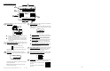
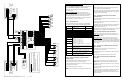
INSTALLATION NOTES:
1. All inputs are shown configured as Normally Open
switches.
2. Lock Relay Outputs (1 & 3) have been configured to
have wet (voltage) outputs. Lock output voltage will be
the same as the UR2-4 input voltage.
3. The Monitoring Relay Output will follow the lock
relay.
12/24 VDC
POWER
SUPPLY
SDC 600
Series
+
-
POWER
P:\INSTALLATION INST\Power Supplies\INST-UR\INST-UR2-4.vsd REV 12-11 Page 9
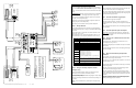
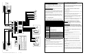
VI. 2-Door Mantrap “B” Setup
Follow the installation steps below before applying power to the UR2-4.
Refer to the MANTRAP “B” MODE wiring diagram on Page 8.
NOTE: It is assumed that the UR2-4 and locking hardware share the
same power supply.
Mantrap “B” Standard Operation:
Both doors are normally closed and locked. Each door may be
individually unlocked using the Access Control System or a remote
release. Unlocking either door causes the other door to be incapable of
being unlocked until the unlocked door returns to its normal state.
The door unlock time will be determined by the Access Control System
and by Dip Switches 2-1 through 2-4 (See Step 1).
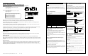
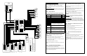
Step 1 – Set Dip Switches
The dip switch settings below are an example of a typical Mantrap B
setup as shown on Page 8. Adjust the dip switch settings as needed.
Step 2 – Configure the Relay Outputs to be Wet
(Voltage) or Dry.
Use the red WET/DRY Selection Jumpers to configure each output.
Refer to Page 2 of this instruction for selection procedure.
On the typical Mantrap B wiring diagram, the Lock Relays (Outputs 1 & 3)
are configured to be wet outputs.
The Monitoring Relays (Outputs 2 & 4) are dry.
NOTE: It is recommended that any unused relays be configured as dry
outputs.
SW1 -1 = ON
Normally Locks Do or #1. This switch must be set ON fo r
M antrap "B " M o de
SW1 -2 = ON
Normally Locks Do or #2. This switch must be set ON fo r
M antrap "B " M o de
SW1 -3 = OFF
SW1 -4 = OFF
SW1 -5 = OFF
SW1 -6 = OFF
SW1 -7 = OFF
SW1 -8 = OFF This switch must be set OFF fo r M antrap "B " M ode
SW2-1 = ON
SW2-2 = OFF
SW2-3 = OFF
SW2-4 = OFF
SW2-5 = OFF
Sets the po larity o f the Do o r M o nito ring Inputs when the
doo r is in the CLOSED and/o r LOCKED po sition.
{OFF = N/O; ON = N/C}
SW2-6 = OFF
Sets the po larity o f Access Co ntrol Inputs when the switch
is in a normal (resting) state. {OFF = N/O; ON = N/C}
SW2-7 = OFF
Sets the o peration of all the M o nitoring Relay Outputs.
{OFF = Relay will fo llo w the Do o r M o nitoring Input;
ON = Relay will fo llo w the Lock Output Relay}
SW2-8 = ON
Switches the UR bo ard between Interlo ck M o de or Contro l
M ode. This switch must be set ON.
SW2-1 through 2-4 set the unlo ck time of the Lock Relay.
N O T E
: This is in additio n to yo ur A ccess Co ntro l System
unlock time.
SW2-1 ON = 5 sec., OFF = 0 sec.;
SW2-2 ON = 1 0 sec., OFF = 0 sec.;
SW2-3 ON = 20 sec., OFF = 0 sec.;
SW2-4 ON = 30 sec., OFF = 0 sec.;
Switch times are additive. {A ll OFF = 1 sec.; All ON = 65
sec.}
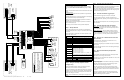
Step 3. Terminate the Lock Power Wiring
Follow the typical Mantrap B wiring diagram for fail-safe or fail-secure
locks. Be careful to observe lock voltage polarity.
NOTE: All low voltage wiring shall be 18-gauge minimum. The minimum
lock power wire gauge shall be determined by the SDC wire gauge chart.
Signal wire shall be 22-guage minimum.
Step 4. Terminate the Access Control and Door
Monitoring Inputs
Connect the Door Monitoring Switches to input terminals A1 & B1. This is
a required connection.
Connect Access Control or remote releases to input terminals A2 & B2.
This is a required connection.
Door Monitoring and Access Control inputs should be dry, Normally Open
or Normally Closed switches, depending on the configuration of Dip
Switches 2-5 and 2-6, respectively.
NOTE: Dip Switch 2-5 configures the normal state of the Door Monitoring
input when the door is in a CLOSED and/or LOCKED position.
Step 5. Terminate Optional Inputs and Outputs
Auxiliary Inputs – These inputs must be wired to dry, Normally Open
switches. The input will only be active when closed (shorted). Refer to
Page 2 for input descriptions.
Monitoring Relay Outputs – Each door station provides a non-fused,
SPDT monitoring relay. This output may be used to signal a Security
Panel or to activate a Remote Annunciator. The relay is configurable as a
Wet or Dry output (Step 2). The relay activation will follow the Lock Relay
or follow the Door Monitoring Input, depending on the configuration of Dip
Switch 2-7 (Step 1).
Step 6. Connect a 12 or 24VDC Power Source to the
UR2-4 Controller.
Before applying power, verify that all the connections are securely
terminated by gently pulling on each wire.
Terminate the voltage wiring to the Controller Power Input. Be careful to
observe polarity.
Verify that both doors are closed & apply power to the controller.
Step 7. UR2-4 Controller Startup and Operation
Verification.
Verify the polarity of the Access Control & Door Monitoring Inputs by
observing the Status Lights located on the lower right of the UR2-4
controller.
Status Lights A1 & B1 will be OFF if Dip Switch 2-5 = OFF, or will be ON
if Dip Switch 2-5 = ON.
Status Lights A2 & B2 will be OFF if Dip Switch 2-6 = OFF, or will be ON
if Dip Switch 2-6 = ON.
Test the standard operation of the mantrap by unlocking a door using the
Access Control System or remote release. The other door will be
incapable of being unlocked until the unlocked door returns to its normal
state (closed & locked).