
Installation manual


11
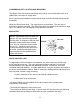
CONDENSING UNIT LOCATION AND MOUNTING
The design of the SA-III allows placement of the unit in an enclosed space such as a
cabin locker, sail locker or engine area.
Service access and installation require that the front and left end (water fitting end) be
accessible.
Mount the Shore Assist level. The compressor is at the bottom. The unit may be
bulkhead or platform mounted. Pilot holes have been pre-drilled for the aluminum angle
clips. Use the #8 x 3/4" self tapping screws which are included.
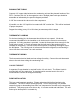
809 PLATES
SEA FROST holdover plates mount with a
"Wellnut" expandable neoprene blind hole
fastener. See the instruction tag packed
With the plate. A template or the part itself
should be used to locate the mounting
holes. Drill 1/4" pilot holes then increase
them to 1/2". Install the screw into the
mounting tab then screw the mount onto
the screw. Install the plate pushing the
rubber mounts into the predrilled holes.
Tighten the screws.
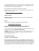
VALVE CONTROL UNIT
For appearance and convenience of installation, the valve control unit (V/CU) may
mount outside the ice box. The valve will attract moisture and drip if it is not well
insulated with the valve blanket and additional insulation. Insulate the valve after
installation and leak checking. In certain applications it may be necessary and easier to
mount the valve inside the cabinet. Refer to schematic drawings when connecting more
than one plate. Before cutting the tubing:
1. leave a minimum of one inch of tube beyond a bulkhead and...
2. allow room for wrench access.
- 90 degree elbows can be installed on the valve control unit to reduce space
requirements if necessary.
- The tubing will support the valve control unit.
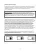
- The tubing must bottom in the fitting. A pencil mark 5/8" from the tube end (3/8 tube)
should be flush with the fitting nut face when the tube is seated in the fitting.