48 OLD CONCORD TURNPIKE BARRINGTON, NH 03825 USA TEL (603) 868-5720 FAX (603) 868-1040 E-Mail:sales@seafrost.com SEA FROST BAIT FREEZER BF1 ~ BF2 ~ BF3 ~ BF5 The Sea Frost Bait Freezer system consists of: • • • • • • 1-800-435-6708 www.seafrost.
OPERATION With the thermostat in the “on” position, the compressor, fan, and pump (if equipped) will operate. Ten minutes after starting the compressor the area near the valve or the top of a hidden coil box will begin to cool and frost. If you do not observe cooling, with the compressor and fan running, switch off the unit to avoid damage. After several hours the box temperature will cool to well below freezing. The first plate or the top section of a wrapped box will cool first.
Water Cooling Water-cooling is standard on BF2 and BF3 models. Water from an air conditioning pump manifold can be plumbed into the BF condensing unit and triggered by the 110volt supply labeled "pump" or a dedicated pump can be installed. A flow of two to three GPM is sufficient. Use of water-cooling is not mandatory; the unit will operate with aircooling only. If the condensing unit is mounted in a confined area with little ventilation, or in a very hot engine room, water-cooling must be used.
Note: Loosen the nut slightly before assembly, and then retighten with your fingers before tightening with a wrench. This avoids cross threading. Swagelok Installation Instructions 1. Always leave two inches of straight, undistorted copper tube leading to all Swagelok fittings to allow proper connection. Measure the tubing the correct distance from the end and mark with a pencil. Refer to Table #1.
Note: Make all connections with two wrenches, do not allow the fittings to turn or twist when tightening. Tighten Swagelok fittings to a torque spec, not infinite tightness. Be sure your starting point is wrench snug. A distorted tube will give a false starting point. Figure 5 ~ Turn the Nut 1 ¼ Turns Reconnecting Pre-Swaged Fittings You can disassemble and retighten Swagelok tube fittings many times. 1. Insert the tubing with pre-swaged ferrules into the fitting body until the front ferrule seats. 2.
Valve Installation on a Wrapped Hidden Coil System Trim the tube ends on the coil as necessary. Allow at least 3/4" of clean, straight tubing to insert into the Swagelok fitting. Refer to the Swagelok installation instructions on page three. Install the valve to supply the top 5/16” tube end on the hidden coil. Position the valve to allow access to the screw cap on top of the valve. The valve cap should be up. Connect a return line to the remaining tube end; this return line connects to the compressor.
Compressor Connections Remove the Swagelok caps from the liquid and suction fittings. Attach the union bodies. This is a pre-swaged connection, which is 1/4 turn from wrench snug. Connect the 1/4" line to the condenser fitting and 5/16" line to the compressor. Tighten these fittings 1 1/4" turns from wrench snug. Thermostat Location The thermostat is low voltage and is connected and powered by the transformer in the compressor cabinet.
Wiring The Ranco Electronic Temperature Control operates on low voltage (24VAC) supplied by the transformer in the compressor cabinet. A 15’ wiring harness is fitted to the thermostat. Use red, blue, and white 16-gauge wire to extend this harness if a longer length is needed. Attach the wires to the terminal strip using #8 ring terminals, matching corresponding wire color.
110-Volt circuit A separate 15-amp breaker is required for the 110-volt supply. A built in transformer powers the thermostat circuit. For operation the BF must have 110-volt power. COMMISSIONING Attach clean, purged gauges to the suction service port on the condensing unit. Connection to the high-pressure port is not necessary when starting a new system. This provides aid in fault diagnosis. 1. Pressurize with nitrogen or R-134a only 2. Check for leaks 3. Evacuate 4.
Start the compressor. The valve must be adjusted to a 0 to 4 psi reading on the low side gauge port. Be sure your gauge is set at O before hook-up. Allow several minutes between each adjustment. Replace the cap after each adjustment to prevent moisture from forming on the adjusting knob; the moisture will freeze and cause the valve to malfunction. The valve must be dry before final cap replacement. Operate for 30 minutes to confirm proper valve setting and operation.
doubt, discharge a suspected overcharged system to continuous foam and slowly add refrigerant to clear the glass. Monitor the sight glass continually. In a warm system, when the cabinet is above freezing (32.F) upon start-up, the sight glass may take several minutes to clear. A cold cabinet may show a clear glass within seconds of startup.
Step 1 Display F or C 2 S1 (blinking) 3 DIF 1 (blinking) 4 C1 / H1 Description Fahrenheit or Celsius Scale Press the set key once to access the Fahrenheit / Celsius scale. The display will show the current status, either F for degrees Fahrenheit or C for degrees Celsius. The thermostat has been pre-set at the factory for Fahrenheit. Press the up or down arrow key to choose between the F and C. Setpoint Temperature Press the set key again to access the setpoint.
TROUBLESHOOTING The low side operating pressure of the system will not indicate the amount of refrigerant in the system. The valve will not give proper operation or pressure if it is undercharged. Check the valve scribe line. It should correlate to gauge pressure. The system requires enough refrigerant to supply liquid to the valve. If the valve has a steady hissing sound then the charge is ok. If the valve is sputtering then it is low. If the valve is making a noticeable roar it is empty.
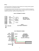
BAIT FREEZER WITH WRAPPED BOX LAYOUT 14
Figure 9 ~ Wrapped Box Layout BAIT FREEZER WITH PLATES LAYOUT 15
Figure 10 ~ Plate Layout 16