372 ROUTE 4 BARRINGTON, NH 03825 USA TEL (603) 868-5720 FAX (603) 868-1040 E-Mail:sales@seafrost.com 1-800-435-6708 www.seafrost.com DC 5000 SYSTEM 134a OPERATION & INSTALLATION INSTRUCTIONS NOTICE OF RESPONSIBILITY It is the SEA FROST/C.F. Horton & Co., Inc. intent to provide the safest, most accurate and detailed instructions. SEA FROST/C.F. Horton & Co.,Inc. cannot be responsible for problems or damage caused by omissions, inaccuracy or interpretation of these instructions.
START UP PROCEDURE AND PERIODIC INSPECTION ATTENTION new SEA FROST owner or operator! PLEASE DO NOT OPERATE THE REFRIGERATION SYSTEM UNTIL YOU READ THIS. WARNING! Your SEA FROST System can be severely damaged and your warranty will be invalid if these steps are not followed closely. Please read the information here before proceeding to operate your system for the first time. BREAK-IN PERIOD. LIMIT COMPRESSOR RUNNING TIMES TO THIRTY MINUTES FOR THE FIRST TWO HOURS OF OPERATION.
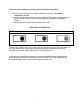
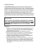
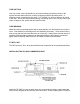
There are three conditions of charge indicated by the sight glass: 1. A black or clear glass and no cooling indicates no charge. Turn off the compressor at once. 2. A white foaming glass and some cooling indicates the system is undercharged or has lost charge. Refer to the manual regarding leak checking and adding charge. 3. A black glass and proper cooling indicates all is well.
TABLE OF CONTENTS OPERATION GENERAL DESCRIPTION ICE MAKING MAINTENANCE HOW REFRIGERATION WORKS INSTALLATION COMPRESSOR INSTALLATION WATER PUMP PLATES VALVE UNIT SWAGELOK FITTINGS, MAKE-UP & RECONNECTING RECEIVER FILTER DRYER ELECTRICAL SYSTEM; WIRING; THERMOSTAT CONTROL PANEL WIRING DIAGRAM ASSEMBLY INSPECTION CHECK LIST REFRIGERANT HANDLING ACCESS TO THE SYSTEM: SERVICE PORTS GAUGES LEAK CHECKING NEW SYSTEM CHARGING READING THE SIGHT GLASS PROPER CHARGE AMOUNT: MAXIMUM CHARGE DISCHARGING THE SYSTEM TROUBLE
GENERAL DESCRIPTION The SEA FROST DC 5000 is a cold storage refrigeration system powered by a 1/2 horsepower permanent magnet direct current 12-volt motor. Refrigerant from the compressor is piped to the SEA FROST plate in the icebox. Cold storage is attained by rapidly freezing the solution contained in the plate, creating a captive (replenishable) block of ice. The system may be used when the boat’s engine is on and charging the batteries or with a properly sized battery bank.
After about one hour (with a single plate), the plate will become very cold. Starting from warm will require more running than the normal refreezing time of the plate in its usable temperature range. The concept of the SEA FROST system is to create as much frozen material in the plate as fast as possible. This "coldness" then keeps the cabinet cold. Daily running times are based on the time needed to freeze enough of the plate to maintain proper cooling. The plate must be frozen.
ICE MAKING WITH VERTICAL TRAYS ON VERTICAL PLATE SYSTEMS Fill the vertical trays with water and hang them on the stainless steel rod on the face of the plate. Try to get some water between the tray and the plate surface to increase the thermal contact to speed freezing. The trays may take time to freeze after the plate is frozen and the compressor has been switched off. HARVESTING VERTICAL TRAYS Plan to wait for the trays to thaw in a sink or away from the plate in the refrigerator.
CLEANING The plate surface protects itself with a layer of oxidation. You might find after a long period of storage the plate will look chalky. This will not effect operation and is easily cleaned up with a pot scrubber and soap. HOW REFRIGERATION WORKS There are two important concepts to understand in order to learn about refrigeration. They are latent heat and phase changes. A great deal of heat is required to change a solid to a liquid, and a liquid to a vapor.
By causing R-134a to boil (evaporate) in the SEA FROST plate, we use the heat energy there. This activity cools the liquid solution within the plate, causing it to change phase (freezing to a solid). By freezing this solution, we have increased its heat absorption capacity more than 100 times. When the cycle is stopped (the compressor is turned off) the frozen plate will begin to absorb the heat that leaks through the insulation in the icebox.
TUBE CUTTING Use only a tube cutter; hacksawing or any other method will introduce chips to the system and also distort the tube, making connections difficult and leak-prone. A miniature cutter is essential for this work. CUT SLOWLY to avoid a ridge on the inside of the tube. We do not recommend reaming or dressing the cut, as it is very easy to get chips of copper in the system that will cause trouble. TUBE BENDING Make all but the long sweep bends with a spring bender; one kink and the line must be rerun.
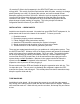
a bulkhead that directly separates the living space from the machine space to avoid excessive sound radiation. The DC 5000 may be installed close to a bulkhead and overhead. Allow access to the front (as shown in the drawing above) and left end where the tubes and hoses will exit. Fasten the DC 5000 through the (4) drilled holes in the base. THE BRUSHES WILL REQUIRE PERIODIC INSPECTION AND REPLACEMENT. BE SURE THE DC 5000 IS LOCATED WHERE BOTH BRUSH COVERS CAN BE ACCESSED.
Install the intake through hull as low in the boat as possible. The minimum size through hull should be 1/2". In areas of floating weed and jelly fish a larger through hull might be beneficial. The sea strainer should be positioned above the through hull with no loops of hose that could trap air. The pump should be positioned above the strainer and pump up to the DC 5000.
VALVE UNIT V/U For appearance and convenience of installation, the valve unit may be mounted outside the icebox. In certain applications and multiple plate systems it may be best to mount it inside. Location of the V/U in multiple plate systems is indicated in the design layout from our application engineer. On an externally mounted V/U two 1/2" Swagelok fittings fasten the V/U to tubing protruding through the icebox wall. Before cutting the tubing: • Leave a minimum of 1 1/4" of tube beyond the bulkhead.
Step 2. Prior to inserting 1/2" tubing into the Swagelok tube fitting, make a pencil mark 1" from end of tube. Prior to inserting 3/8" tubing, make a pencil mark 3/4" from the end of the tube. With 1/4" tubing make a mark 5/8" from the end. Step 3. Insert clean, smooth tubing with the pencil mark into the Swagelok tube fitting. You can be sure the tube is resting firmly on the shoulder of the fitting when the pencil mark is flush with the nut.
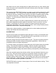
STEP 2 Before tightening the SWAGELOK nut, scribe the nut at the six o'clock position. STEP 3 Now, while holding the fitting body steady with a backup wrench, tighten the nut 1 1/4 turns. Watch the scribe mark, make one complete revolution and continue to the 9 o'clock position. By scribing the nut at the 6 o'clock position as it appears to you, there will be no doubt as to the starting position.
SWAGELOK PERFORMANCE Swagelok fittings have built-in spring interaction between the ferrules. This compensates for temperature changes, vibration loosening and allows the fittings to be reconnected many times. As the fitting is tightened, a burnishing occurs between the body of the fitting and the ferrules and between the ferrules and the tube. This action provides a leak proof connection. RUNNING THE LINES See the schematic diagram. Prior to making up connections see "Swagelok Fittings" texts.
PLANNING 1. Keep tube runs as short as possible. The suction (return) line should be as direct as possible with a minimum number of bends. 2. Tape the 1/4" line and the 1/2" line together in the section between the V/U and the DC 5000. This is for thermal exchange (sub cooling). POSITIONING THE RFD • The RFD is fitted with a sight glass. This glass must be visible for charging and servicing the system. It can be viewed from the top at up to a 45-degree angle but not from the bottom or side.
RFD (Receiver Filter Drier) DO NOT OPEN THE RFD UNTIL ALL THE OTHER CONNECTIONS HAVE BEEN MADE AND YOU ARE READY TO COMMISSION THE SYSTEM. Because the RFD contains desiccant to absorb moisture and the absorption is limited, it is important to unpack and install it after all other connections are made. Leaving the RFD installed on a partially open system may reduce its capacity by allowing it to absorb moisture in free air before the system is sealed. The RFD is a reservoir for excess refrigerant.
CABLE TIES Cable Ties should be used to support the wiring, tubing, and insulation. There is a screw hole in the end of each tie that is used for mounting. Loosely loop the tie, mount the screw loosely, snug the wrap, tighten the screw, and trim the excess. Be sure not to leave a sharp end on the cable tie. ELECTRICAL SYSTEM The electrical system for the DC 5000 system includes a Thermostat Control Panel with pilot light, and a junction box with solenoid.
THERMOSTAT CONTROL PANEL LOCATION The Thermostat Control Panel should be outside the box in order to protect it and to allow observation of the indicator lamp. The length of the sensing tube dictates the location, as it must reach the plate. The maximum length of this tube is 40" (180 mm.) (The sensing tube must be attached to the refrigerator plate in a multiple plate system.) Mount the Thermostat in a location where the wires and sensing tube can be led.
WIRE SIZES This information is to be used as a guide only. Please make sure your wiring meets or exceeds all applicable standards. The DC 5000 must be wired with heavy gauge wire from the batteries to the Electrical Junction Box in order to supply the proper current and voltage. Follow the chart below based on the ABYC specifications allowing a 10% voltage drop. If possible use the next larger size. These distances are from the batteries to the Electrical Junction Box.
The positive and negative cable total length must not exceed twice the distance listed above. Be sure your wire length calculation is from the batteries not the connection points of the supply wires. (It is assumed that heavier cable is used to supply an electrical junction like the battery switch or buss bar.) FUSES Fuse the 12-volt positive wire from the battery to the Electrical Junction Box with a 50amp fuse. The fuse location should be as close as possible to the battery or selector switch.
[ ] 4. Check all the hose clamps for tightness. [ ] 5. Check the neatness of the installation, sufficient service access, secure wiring, and make sure tubing and hoses are supported to prevent damage and chafing. [ ] 6. Check the service access. The service access ports must allow attachment of the connecting service valves. [ ] 7. Check (after leak checking and testing) that the tubing is properly insulated.
WARNING NEVER OPERATE a system WITH THE HIGH side (discharge) OPEN TO the REFRIGERANT supply. Pressurization of the refrigerant container could cause it to burst. WARNING. When charging or working on the system installed in an engine room with the engine running, watch for MOVING BELTS AND PULLEYS. Loose clothes and long hair can pull you into a belt. PLEASE BE CAREFUL. PROCEDURES FOR WORKING WITH R-134a 1) A new uncharged system must be evacuated before adding R-134a.
GAUGES Gauges must be used in the evacuation and charging. They will provide information on the operation of the system when troubleshooting. A gauge sets consist of two gauges installed in a manifold with two hand wheel valves and hoses to connect the gauges to the system. The left gauge (blue) is a compound device; it indicates pressure and also vacuum. The right gauge (red) indicates pressure only. The hand wheels open a center port (yellow) to the left or right side respectively.
CONNECTING GAUGES To connect service gauges to the access service ports, remove the protective sealing caps from the service ports on the DC 5000. Note that the ports are of different sizes. The larger diameter port is the discharge side and the smaller port is the suction side. Pull back the collar on the connecting valve and push it over the appropriate access port.
VENTING THE GAUGE SET To connect the gauges to a charged system if the gauge set has not been purged with refrigerant, attach the service valves to the system and vent the hoses at the manifold body by opening the hand wheels to an open center hose for a few seconds allowing some of the system refrigerant to purge the hoses of air. If the center hose is fitted with a check valve it will not be purged and must be purged with the refrigerant supply before introducing charge.
COMMISSIONING PROCEDURE EVACUATION WITH A VACUUM PUMP Evacuation removes air, readying the system for charging. Connect a gauge set to the service access ports. Connect the gauge center hose to a high vacuum pump. Start the pump and slowly open the suction gauge hand wheel. As the vacuum drops below 20 inches open both hand wheels fully. EVACUATION LEAK TEST Evacuate the system to the best vacuum (lowest pressure). Close the hand wheels to the pump.
LEAK CHECKING A CHARGED SYSTEM ABOUT PRESSURES Refrigerant in a saturated condition, part liquid and part vapor will exert a pressure that is a function of its temperature. The higher the temperature, the higher the pressure. Avoid leak checking in cold weather. A refrigerant leak will show with moderate pressure. A leak is not a function of pressure. Pressure is only required to aid in detection.
NOTE: Propellants and solvents (sprays and foams) may upset electronic detectors. To confirm a leak detected with a detector use bubbles and be sure it is a leak and not some erroneous vapor that is upsetting the machine. Electronic detectors do not function below 40.F. A good leak detector is able to pick up leaks as low as 1/2 oz. per year. NEW SYSTEM CHARGING 1. Continue after a thorough leak check by opening the discharge (red) gauge hand wheel valve with the can inverted to introduce more refrigerant.
8. Leak check the capped connection service ports with the leak detector. 9. Spray the acrylic coating, or similar rust inhibitor, on all the fittings and components when they are dry. 10. Finish insulating the V/U, suction line and any suction line connectors. 11. BREAK-IN PERIOD. During the first four hours of operation of a new compressor, limit the compressor running times to thirty minutes with an hour rest period.
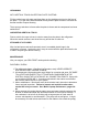
RFD SIGHT GLASS DETAIL CLEAR (or empty) STATIONARY BUBBLES FOAM (low charge) PROPER CHARGE AMOUNT THE DC 5000 SYSTEM IS DESIGNED TO HOLD 24 OUNCES. THIS IS EQUAL TO 2 CANS OF R-134a AS SUPPLIED WITH THE SYSTEM. THIS IS THE MAXIMUM CHARGE. The sight glass must clear by the time the return line to the compressor goes below 32 degrees F. GENERAL INFORMATION Operating pressures will vary with, water temperature, and water flow. Generally, the discharge pressure will peak with a warm plate in five minutes.
DISCHARGING THE SYSTEM Before the connections or components can be disassembled, the refrigerant must be recovered with a reclaiming machine. Connect a gauge set to the suction access port and slowly recover the refrigerant. Keep the pressure under 20 psi. Do not loosen any connections until the system holds 10 inches of vacuum for 10 minutes. To discharging an overcharged system; recover at the same 20 psi rate for a minute at a time between test operations.
b) If the pressure readings are over 50 psi with the compressor off, proceed to check charge level via sight glass and charge if needed. Charge loss indicates a leak that must be corrected. STEP 2. If the system continues to operate improperly after Step 1, check for moisture or dirt plugging the valve. Run the system, observing closely the gauge readings and plate temperature, noting the following.
Recharge. Refer to "New System Charging". MOISTURE IS A SYMPTOM. Carefully leak check the low side of the system if moisture becomes a problem. Moisture leaks in! Technical help 603-868-5720 TOLL FREE IN THE UNITED STATES, CANADA, AND CARIBBEAN 800-435-6708 E-mail sales@seafrost.
PRESSURE CHARTS 36
PRESSURE CHARTS 37
PRESSURE CHARTS 38
DC 5000 MOTOR AND WATER PUMP MAINTENANCE Lubrication The DC 5000 motor and the March water pump are supplied with lifetime lubricated ball bearings. Brushes (Leeson Motor) Motor brushes need periodic inspection and replacement as wear indicates. Brush wear is greatly influenced by individual application, voltage and heat load. It is recommended that brush wear be checked at early intervals of operation in order to determine future required inspection.
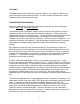
Tip: In a new motor with new brushes the back of the brush will be flush with the brush housing, as the brush wears the distance into the housing will increase. (See top view drawing below.) A quick measurement of the depth will be sufficient. When the brush is 5/8” into the holder it will need replacement. If in doubt change the brushes. Carry spares. When changing brushes, be sure the phillips screw holding the brush wire and power lead is tightened properly to assure a good electrical connection.
DC5000 WIRING 41
DC 5000 LAYOUT 42
DC 5000 WATER CIRCUIT 43
TWIN VALVE SYSTEMS ONLY 44
DC 5000 Low Voltage Protection Relay The DC 5000 uses a Macromatic relay to monitor the voltage at the compressor motor. The relay has an adjustable pick up voltage (reset). A red indicator lamp lights when the relay is on. This lamp turns green when the relay senses low voltage and turns off. This relay is designed to protect the compressor motor from low voltage damage as well as protecting the batteries from deep discharge. How It Works As an example, if the pick up voltage is set at 12.