
Installation guide

INSTALLATION HC-229
FINAL ASSEMBLY
STEP 1:
S
TEP 6:
I
MPORTANT: DO NOT ATTACH FIXTURE DIRECTLY TO OUTLET
BOX.
S
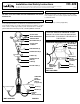
ecure mounting bar (A) to outlet box with outlet box screws (not
supplied). Thread nut (B) on nipple (C) so that 3 threads are
exposed above nut (B). Thread nipple (C) into mounting bar (A) and
secure with nut (B). Attach screw collar (E) to nipple (C).
STEP 2:
Using 2 pairs of pliers, open one link of chain (S) and connect it to
the fixture loop (I) at the top of the fixture.
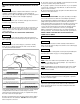
A. Take note of the color of the wire(s) on your fixture. Identify
which group your fixture wire(s) falls into and connect the wires
according to the directions below:
STEP 3:
STEP 4:
STEP 5:
Slide the screw collar ring (G) and canopy (H), in that order, over
chain (S). Open one link on the other end of the chain (S) and
attach it to the screw collar (E) which has been mounted to the
ceiling nipple (C).
BE SURE TO CLOSE ALL CHAIN LINKS COMPLETELY.
Lace wires up through chain (S) and pass wires through holes in
screw collar (E). We recommend lacing wire up through every other
link of chain (S).
*Note: When parallel wire is used, the tracer wire is square shaped
or ridged and less tracer wir
e is r
ound in shape or smooth.
(Seen best when viewed fr
om wir
e end.) T
o separate wir
es, grasp
the ends of each wire and pull apart.
B. Take your fixture wire(s) from group A and place evenly against
the black wire from the outlet box.
DO NOT twist wires together
before using wire connectors.
C
.
F
it a wire connector (not supplied) over the wires and screw the
connector clockwise until you feel a firmness.
D. Try gently to pull the connector off the wires. If you can pull the
c
onnector off, carefully re-do steps B and C, as above and check
again for a firm connection.
E. Connect the fixture wire from group B to the white wire from the
o
utlet box in the same manner.
GROUNDING INSTRUCTIONS: The green grounding screw (D) is
t
o be inserted into the hole with two raised dimples provided on
the mounting bar (A). Wrap the ground wire (F) from the fixture (if sup-
plied) and the ground wire from the outlet box (bare metal or
g
reen insulated wire) around the green grounding screw (D) on the
mounting bar (A) if uninsulated wire is on the mounting bar (A),
connect the ground wire (F) from the fixture (if supplied) and the
outlet box to it using a small wire connector (not supplied).
NOTE: Underwriters Laboratories does not require all fixtures to
have ground wires. These fixtures still meet all UL specifications.
NEVER CONNECT GROUND WIRE TO BLACK OR WHITE
POWER SUPPLY WIRES.
GROUP A: CONNECT TO BLACK
HOUSE WIRE
BLACK
WHITE
*
P
ARALLEL
WIRE (ROUND & SMOOTH)
WHITE OR GREY WITH TRACER
BROWN,
GOLD OR BLACK
WITHOUT TRACER
BROWN, GOLD OR BLACK WITH TRACER
WHITE OR GREY
WITHOUT TRACER
*PARALLEL WIRE (SQUARE & RIDGED)
GROUP B: CONNECT TO WHITE
HOUSE WIRE
Slide glass (J) over socket (K) and secure in place by threading the
threaded glass retainer ring (L) on socket (K) (If applicable).
Install lamps.
NOTE: Due to the variation among hand blown glass shades
(diffusers), your fixture may not hang straight. Try to reposition or
switch the glass shades around.
NOTE: (If applicable) If not enough threads are exposed on candle
cover for glass retaining ring (L) to hold down glass (J), unscrew
candle cover as needed.
CLEANING
ORDERING PARTS
To clean, wipe fixture with a soft cloth. Clean glass with a mild soap.
Do not use abrasive materials such as scouring pads or powders,
steel wool or abrasive paper.
Keep this sheet for future reference, and in case you need to order
replacement parts. All parts for this fixture can be ordered from
place of purchase. Be sur
e to use exact wording from illustration
when ordering parts.
STEP 1:
STEP 2:
STEP 3:
After wires are connected, tuck them carefully inside outlet box.
Raise canopy (H) against ceiling and screw the screw collar ring (G)
to the screw collar (E).
Make sure no bare wires can be seen outside wire connectors.