
Installation Guide
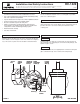

GROUNDING INSTRUCTIONS: The green grounding screw (G) is to
be inserted into the hole with two raised dimples provided on the
universal mounting bar (D). Wrap the fixture ground wire (H) and the
ground wire from the outlet box (bare metal or green insulated wire)
around the green grounding screw (G) on the universal mounting bar
(D) and tighten the green grounding screw (G) to secure.
NEVER
CONNECT GROUND WIRE TO BLACK OR WHITE POWER
SUPPLY WIRES.
INSTALLATION (continued) HC-1429
STEP 3:
A
.
U
se a listed wire connector to connect the fixture hot wire (black
wire, or round and smooth tracer) to the supply hot wire.
B. Use a listed wire connector to connect the fixture common wire
(white wire, or square and rigid) to the supply common wire.
C
.
G
ently try to remove the wires from the connector. If you can
remove the wires, carefully re-do the wiring connection.
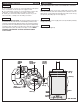
STEP 4:
M
ake sure no bare wires can be seen outside wire connectors. After
wires are connected, tuck them carefully inside outlet box. Push the
fixture firmly over the nipple (F) and against the wall. Secure canopy
(I) in place by threading cap nut onto nipple (F).
Make sure no bare wires can be seen outside wire connectors.
Install lamps (not supplied).
P
lace shade (A) on socket cup (B) and secure by threading retaining
ring (C) onto socket.
FINAL ASSEMBLY
STEP 5:
STEP 6:
STEP 7:
*NOT INCLUDED
NUT (E)
SHADE (A)
RETAINING
RING (C)
NIPPLE (F)
GREEN
GROUNDING
SCREW (G)
FIXTURE
GROUND
WIRE (H)
*WIRE
CONNECTORS
SOCKET
CUP (B)
CANOPY
(I)
STEP 6
*HOUSE
GROUND
WIRE
STEP 3
STEP 4