
Installation Guide
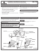


*PARALLEL WIRE (ROUND & SMOOTH) *PARALLEL WIRE (SQUARE & RIDGED)
B
LACK WHITE
GROUP A:
CONNECT TO BLACK HOUSE WIRE
GROUP B:
CONNECT TO WHITE HOUSE WIRE
GROUNDING INSTRUCTIONS: Wrap the ground wire from the
fixtur
e (if supplied) and the ground wire from the outlet box (bare
metal or green insulated wire) around the green grounding screw (B)
on the back plate (A); (Or if applicable).The green grounding screw is
to be inserted into the hole with two raised dimples provided on the
back plate (A).
NEVER CONNECT GROUND WIRE TO BLACK OR WHITE POWER
SUPPLY WIRES.
INSTALLATION (continued) HC-118
STEP 3:
A
.
T
ake note of the color of the wire(s) on your fixture. Identify which
group your fixture wire(s) falls into and connect the wires according
to the directions below:
STEP 4:
I
nstall lamp.
Make sure no bare wires can be seen outside wire connectors.
To install glass (E) on fixture with retaining screws (F), slip lip of glass
(E) into holder (C), push glass (E) against wall and secure in place
with retaining screws (F).
Place banding (G) on glass (E) lip and bend tabs around glass (E). (If
applicable.)
FINAL ASSEMBLY
STEP 6:
STEP 7:
STEP 8:
A. Take note of the color of the wire(s) on your fixture. Identify which
group your fixture wire(s) falls into and connect the wires according
to the directions below:
*Note: When parallel wire is used, the tracer wire is square shaped or
ridged and less tracer wire is round in shape or smooth
(Seen best when viewed from wire end). To separate wires, grasp the
ends of each wire and pull apart.
B. Take your fixture wire(s) from group A and place evenly against
the black wire from the outlet box. DO NOT twist wires together
before using wire connectors.
C. Fit a wire connector (not supplied) over the wires and thread the
connector clockwise until you feel a firm resistance.
D. Gently try to remove the wires from the connector, If you can
remove the wires, carefully re-do steps B and C, as above and check
again for a firm connection.
E. Connect the fixtur
e wire from group B to the white wire from the
outlet box in the same manner.
Tuck wires into outlet box. Attach backplate (A) to outlet box by
placing outlet box screws (not supplied) through punched out holes
in backplate (A).
STEP 5:
FOR SEA GULL FIXTURES: X4160 AND X4777. THE
LAMP MUST BE A MINIMUM OF 1 7/8" AWAY FROM
THE WALL. IF NOT BEND THE LAMP HOLDER AWAY
F
ROM THE WALL TO MEET THIS REQUIREMENT.
N
OTE:
I
t may be necessary to slightly bend the
sockets forward to allow for lamp installation.
To install glass (E) with adjustable cup (B), slide bottom of glass (E) in
between cup (B) and bottom of backplate (A), press glass (E) firmly
against wall and tighten with adjusting screw (D).
STEP 9:
Use screws (H) provided to secure banding (G) to wall. Do not
overtighten.
NOTE: It may be necessary to adjust angle of backplate (A) flange to
make glass seat against wall. This can be done by bending
backplate (A) flange upward. (See Fig. 1)
STEP 10: