
Installation Guide

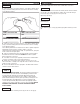

FIGURE 1 *NOT INCLUDED
Installation And Safety Instructions
Line art shown may not exactly match the fixture enclosed. However, the installation instructions do apply to
this fixture. Fill in Item Number on Carton and File This Sheet For Future Reference. ITEM#_______________
HC-167
0
80708
Car
efully remove the fixture from the carton and check that all parts
are included, as shown in figure 1. Be careful not to misplace
any of the screws or parts which are needed to install this fixture.
•
Be sure the electricity to the system you are working on is turned
off; either the fuse removed or the circuit breaker set at off.
• Use of other manufacturers components will void warranty, listing
and create a potential safety hazard.
• If you are unclear as to how to proceed, contact a qualified electrician.
•
You don’t need special tools to install this fixture.
• Be sure to follow the steps in the order given.
• Under no circumstances should a fixture be hung on house
electrical wires, nor should a swag type fixture be installed on a
ceiling which contains a radiant type heating system.
• Read instructions carefully.
•
Save these instructions.
IMPORTANT SAFETY INSTRUCTIONS
BEFORE YOU BEGIN
To clean, wipe fixture with a soft cloth. Clean glass with a mild soap.
Do not use abrasive materials such as scouring pads or powders,
steel wool or abrasive paper.
Keep this sheet for future reference, and in case you need to order
replacement parts. Parts for this fixture can be ordered from place of
purchase. Be sure to use exact wording from illustration when
ordering parts.
CLEANING
ORDERING PARTS
IMPORTANT: DO NOT ATTACH FIXTURE DIRECTLY TO OUTLET BOX.
INSTALLATION
NOTE: FOR FIXTURES PROVIDED WITH 75˚C OR 90˚C SUPPLY WIRE
WARNING ONLY-(THESE WARNINGS ARE PROVIDED ON THE LABEL
AND ON THE FIXTURE CARTON): RISK OF FIRE. MOST DWELLINGS
BUILT BEFORE 1985 HAVE SUPPLY WIRE RATED 60˚C. CONSULT A
QUALIFIED ELECTRICIAN BEFORE INSTALLING.
FIGURE 2 *NOT INCLUDED
Secur
e mounting bar (A) to outlet box with outlet box scr
ews (not
supplied). Thr
ead nut (B) on nipple (C) so that 3 thr
eads ar
e exposed
above nut (B). Thread nipple (C) into mounting bar (A) and secure
with nut (B).
STEP 1:
*OUTLET BOX
*WIRE
CONNECTOR
MOUNTING
BAR (A)
NUT (B)
NIPPLE (C)
RETAINING
SCREW (E)
CAP NUT (F)
*GROUND
WIRE
*OUTLET
BOX SCREWS
CANOPY
(Z)
CENTER
HOLE
(K)
*OUTLET
BOX
SCREWS
MOUNTING
BAR (A)
*WIRE
CONNECTORS
*GROUND WIRE
*OUTLET BOX
GROUNDING AND MOUNTING
BAR LOCK UP
NIPPLE (C)
NUT (B)
GREEN
GROUNDING
SCREW (D)
DIFFUSER
(G)