
Installation Guide

Installation And
Safety Instruction
HC-558
042408
Line art shown may not exactly match the fixture enclosed.
Ho
wev
er
, the installation instructions do apply to this fixture.
F
ill In Item Number On Carton
And
File This Sheet For Fixture Reference. ITEM#_______________
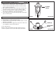
1. Snap lamp into lamp holder (K) by inserting lip of lamp (L)
between ears on lamp holder (K). Insert lamp into socket (J).
2. Press lamp assembly into housing (A) and push fixture
shroud (B) onto housing (A).
3. Secure with set screw (C).
NOTE: LENS RETAINING RING IS USED FOR OPTIONAL
LOUVERS OR GLASS ACCESSORIES
Lighted lamp is HOT!
TO REDUCE THE RISK OF FIRE OR INJURY TO PERSONS:
1. Turn off and allow to cool before replacing lamp.
2.
Lamp gets HOT quickly! Contact switch only when turning on.
3. Do not touch hot lens, guard, or housing.
4. Keep lamp away from combustible materials.
5. Do not touch the lamp at any time. Use a soft cloth.
Oil from skin may damage lamp.
6. Do not operate the fixture with a missing or damaged shield.
7. Do not install within 10 feet (1.52m) of a pool, spa, or fountain.
INSTALLATION AND SAFETY INSTRUCTIONS HC-558
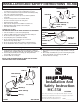
FIXTURE SHROUD (B)
*LAMP
LEAD CONNECTORS (G)
HOUSING (A)
SWIVEL SCREW (E)
NIPPLE (I)
*NOT SUPPLIED
TERMINAL
SCREW (F)
LEAD
CONNECTORS (G)
LAMP
TERMINAL (H)
*50W PAR 36
LAMP MAX
FIGURE 2
S
ET
SCREW
(C)
FIXTURE SHROUD (B)
LAMP HOLDER (K)
*LAMP (L)
SOCKET (J)
HOUSING (A)
SWIVEL SCREW (E)
NIPPLE (I)
SET SCREW (C)
• Be sure the electricity to the system you are working on is turned
off; either the fuse removed or the circuit breaker set at off.
• Use of other manufacturers components will void warranty, listing
and create a potential safety hazard.
• If you are unclear as to how to proceed, contact a qualified
electrician.
•
You don’t need special tools to install this fixture.
• Be sure to follow the steps in the order given.
• Read instructions carefully.
• Risk of shock. 24V system not suitable for outdoor use.
• Dimming halogen lamps greatly reduces lamp life.
• Save these instructions.
IMPORTANT SAFETY INSTRUCTIONS
*NOT SUPPLIED
FIGURE 3
*NO
T SUPPLIED
FIGURE 1
ASSEMBLY # 9223, 92061 (Figure 1)
1. Attach lead connectors (G) to lamp terminal screw (F)
(FIG. 3).
2. Press lamp assembly into groove in housing and push
fixture shroud (B) onto housing (A) (FIG. 2).
3. Secure with set screw (C).
ASSEMBLY # 9227, 92062 (Figure 2 & 3)