INSTALLATION MANUAL FOR SEA TEL 6012-33 KU-BAND BROADBAND-AT-SEA VSAT ANTENNA SYSTEM Sea Tel, Inc. 4030 Nelson Avenue Concord, CA 94520 Tel: (925) 798-7979 Fax: (925) 798-7986 Web: http://www.cobham.com/seatel Sea Tel Europe Unit 1, Orion Industrial Centre Wide Lane, Swaythling Southampton, UK S0 18 2HJ Tel: 44 (0)23 80 671155 Fax: 44 (0)23 80 671166 Web: http://www.cobham.com/seatel Sea Tel Inc is also doing business as Cobham SATCOM - Maritime November 20, 2013 Document. No.
These commodities, technology or software were exported from the United States in accordance with the Export Administration Regulations. Diversion contrary to U.S. law is prohibited. Sea Tel Marine Stabilized Antenna systems are manufactured in the United States of America. Sea Tel is an ISO 9001:2008 registered company. Certificate Number 13690 issued March 14, 2011.
Cobham SATCOM Marine Systems, Sea Tel Products 4030 Nelson Ave., Concord California, 94520 USA Tel: +1 (925) 798-7979 Fax:+1 (925) 288-1420 R&TTE Declaration of Conformity Sea Tel Inc. declares under our sole responsibility that the products identified below are in compliance with the requirements of: DIRECTIVE 1999/5/EC of the European Parliament and of the Council of 9 March 1999 on Radio equipment and Telecommunication Terminal Equipment and the mutual recognition of their conformity.
Sea Tel Inc. 4030 Nelson Ave., Concord California, 94520, USA T: +1 (925) 798-7979 F: +1 (925) 798-7986 FCC Declaration of Conformity 1. Sea Tel, Inc. designs, develops, manufactures and services marine stabilized antenna systems for satellite communication at sea. These products are in turn used by our customers as part of their Kuband Earth Station on Vessels (ESV) networks. 2. FCC regulation 47 C.F.R. § 25.222 defines the provisions for blanket licensing of ESV antennas operating in the Ku Band.
Table of Contents 1. 2. 3. 6012-33 Installation Manual SERIES 12 KU-BAND SYSTEM CONFIGURATION(S)........................................................................................................... 1-1 1.1. SYSTEM CABLES ............................................................................................................................................................................................. 1-1 1.2. OTHER INPUTS TO THE SYSTEM .......................................................
012-33 Installation Manual 4. 5. 6. 7. 8. 9. 10. 11. 12. 13. 14. Table of Contents 3.7.3. Media Xchange Point™ (MXP) Connections ................................................................................................................ 3-9 3.7.4. Other BDE connections ...................................................................................................................................................... 3-12 3.8. FINAL CHECKS....................................................
Table of Contents 15. 16. 17. 18. 19. 6012-33 Installation Manual 14.3. IF SATELLITE SIGNAL IS FOUND BUT NETWORK LOCK IS NOT ACHIEVED:.........................................................................................14-3 14.4. TO TARGET A DIFFERENT SATELLITE ........................................................................................................................................................14-4 OPTIMIZING CROSS-POL ISOLATION ....................................................
6012-33 Installation Manual Table of Contents This Page Intentionally Left Blank viii
Series 12 Ku-Band System Configuration(s) 1. 6012-33 Installation Manual Series 12 Ku-Band System Configuration(s) The Series 12 Ku-Band Stabilized Antenna system is to be used for Transmit/Receive (TX/RX) satellite communications. It is comprised of two major groups of equipment: the Above Decks Equipment (ADE) and the Below Decks Equipment (BDE). There will also be interconnecting cables between the ADE & BDE and cables to provide other inputs to the system.
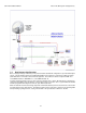
6012-33 Installation Manual 1.4. Series 12 Ku-Band System Configuration(s) Dual Antenna Configuration Due to very large blockage conditions, you may need to install a dual antenna configuration to provide uninterrupted services. Two full antenna systems are installed and the MXP control outputs are connected to an arbitrator switch panel which then is connected to the below decks equipment. The connection scheme is required for MXP “A” to control ONLY Antenna “A” AND MXP “B” to control ONLY Antenna “B.
Series 12 Ku-Band System Configuration(s) 1.5. 6012-33 Installation Manual Open Antenna-Modem Interface Protocol (OpenAMIP™) Specification: 1.5.1. Overview: OpenAMIPTM, an ASCII message based protocol invented and Trademarked by iDirect, is a specification for the interchange of information between an antenna controller and a satellite modem.
6012-33 Installation Manual Series 12 Ku-Band System Configuration(s) Utilized OpenAMIPTM Commands: 1.5.3. 1.5.3.1.
Site Survey 2. 6012-33 Installation Manual Site Survey There are three objective of the site survey. The first is to find the best place to mount the antenna and the BDE. The second is to identify the length and routing of the cables and any other items or materials that are required to install the system. The third is to identify any other issues that must be resolved before or during the installation. 2.1.
6012-33 Installation Manual 2.3. Site Survey Mounting Foundation 2.3.1. Mounting on Deck or Deckhouse While mounting the ADE on a mast is a common solution to elevate the ADE far enough above the various obstructions which create signal blockages, sometimes the best mounting position is on a deck or deckhouse top. These installations are inherently stiffer than a mast installation, if for no other reason than the design of the deck/deckhouse structure is prescribed by the ship’s classification society.
Site Survey 6012-33 Installation Manual 9. 2.4. foot rung should be added. Additional rungs should be added for every 0.3 meter (12 inches) of pedestal height above the ship’s structure. For an ADE mounted greater than 3 meters (9 feet) above the ship’s structure, a fully enclosing cage should be included in way of the access ladder, starting 2.3 meters (7 feet) above the ship’s structure.
6012-33 Installation Manual 2.5.1. Site Survey Vertical Masts Vertical masts are a very ancient and common mast design. In essence, it is the mast derived from the sailing mast and adapted for mounting the ever-increasing array of antennae which ships need to communicate with the world. This drawing of a vertical mast shows the preferred mounting of the ADE center-line above the plane of the radar.
Site Survey 6012-33 Installation Manual 2.5.4. Truss Mast Truss masts are a variant on the girder mast concept. Rather than a pair of columns supporting a girder beam, the construction is a framework of tubular members supporting a platform on which the antennae and other equipment are mounted. A typical truss mast is shown in this photograph. Like a girder mast, truss masts are especially stiff in the athwart ship direction.
6012-33 Installation Manual 2.8.1. Site Survey ADE/BDE Coaxial Cables The first concern with the coaxial cables installed between the ADE & BDE is length. This length is used to determine the loss of the various possible coax, Heliax or fiber-optic cables that might be used. You should always provide the lowest loss cables to provide the strongest signal level into the satellite modem.
Site Survey 2.9. 6012-33 Installation Manual Grounding All metal parts of the ADE shall be grounded to bare metal that is common to the hull of the ship. This is most commonly accomplished by attaching a ground wire/cable from the upper base plate ground point to a ground stud on the mounting pedestal/stanchion/mast near the base of the radome. Preservation of the bare metal contact point should be done to prevent loss of ground due to rust and/or corrosion.
6012-33 Installation Manual Site Survey This Page Intentionally Left Blank 2-8
Installation 3. 6012-33 Installation Manual Installation Your antenna pedestal comes completely assembled in its radome. This section contains instructions for unpacking, final assembling and installing of the equipment. It is highly recommended that trained technicians install the system. The installation instructions for your system are below. 3.1. Unpacking and Inspection Exercise caution when unpacking the equipment. 1. Unpack the crates.
6012-33 Installation Manual 3.3. Installation Installing the ADE The antenna pedestal is shipped completely assembled in its radome. Please refer to the entire Site Survey chapter of this manual. Base Hatch Access - Mounting the radome directly on the deck or platform prevents access to the hatch in the base of the radome unless an opening is designed into the mounting surface to allow such entry. If there is no access to the hatch the only way to service the antenna is to remove the radome top.
Installation 6012-33 Installation Manual 6. 7. 8. 3.3.2. Attach shackles and four part web lifting sling arrangement to the eyebolts. Attach a suitable length tagline to one of the eyebolts. After hoisted into place the lifting eyes are to be removed and replaced with the stainless hardware that was removed in step 4 (the eyes are galvanized with bare thread that will rust if left exposed to the weather). Install 76” Radome to mounting deck.
6012-33 Installation Manual 3.3.3. Installation Preparing and Installing the Single Piece 81” Radome Assembly The antenna pedestal is shipped completely assembled in its 81” single piece radome. 1. Remove the shipping hold-down bolts which mount the ADE to its’ pallet. 2. Install four lifting eye bolts, provided in the radome installation kit, in holes around the perimeter of the baseframe. 3.
Installation 6012-33 Installation Manual 1. Connect the ground wire (of adequate gauge for the length) to a burnished ground point on, or near, the mounting surface. This burnished grounding point must be electrically common with the hull. Bi-metal coupling plate may be required to get good electrical coupling to the hull of the ship. Protective coating should be applied to prevent the grounding point, and ground wire, from rusting or corroding.
6012-33 Installation Manual 3. 4. Installation Install the pin bolt into the STOW hole and tighten. This assures that it does not get lost and will be ready for re-use if the antenna needs to be stowed again at a later date. Verify that the antenna is able to rotate freely in azimuth. 3.5.2. 1. 2.
Installation 6012-33 Installation Manual 3. 4. 5. 6. 7. To un-restrain the elevation axis of the antenna, unthread the two hex nuts. Using a ¾” open end wrench, remove the hex nuts and washer from the stow pin-bolt. Remove the stow pin-bolt from the bracket. Remove the washer from the stow pin-bolt and thread one of the two hex nuts onto the bolt and tighten. Put one of the washers onto the stow pin-bolt and insert it into the bracket toward the elevation driven sprocket.
6012-33 Installation Manual 8. 9. 3.5.3. 1. Installation Tighten the hex nut to prevent the hardware from loosening while in the un-stowed configuration. Verify that the antenna rotates freely through its full elevation range of motion. Removing the CL Shipping/Stow Restraint The CL shipping/stow restraint is formed by a red locking bar with adjustable bumpers at each end of the bar. This mechanism is placed under the cross-level beam to lock it in place.
Installation 6012-33 Installation Manual 5. 6. 3.6. Extract the locking bar from the underside of the cross-level beam and retain these parts for later re-use if it becomes necessary to stow the antenna. Verify that the antenna rotates (tilts left and right from level) freely through its full crosslevel range of motion. Installing the Below Decks Equipment. 3.6.1. General Cautions & Warnings CAUTION - Electrical Shock Potentials exist on the Gyro Compass output lines.
6012-33 Installation Manual Installation 3.7.3.1. Ships AC Mains Connect the power cord from the rear panel of the MXP to AC voltage power source (UPS power recommended). 3.7.3.2. J1 Modem RX Connect this RXIF Output to the satellite modem RX Input using an appropriate coaxial cable. 3.7.3.3. J2 Antenna RX Connect this RXIF Input from the antenna to this port on the rear panel of the MXP using coaxial cable provided 3.7.3.4.
Installation 6012-33 Installation Manual 3.7.3.1. J13 NMEA 0183 NMEA 0183 I/O connections. Wiring is: Pin 1 Pin 2 Pin 3 Pin 4 Pin 5 Pin6 Pin 7 Pin 8 Pin 9 RX+ RXTXN/C GND N/C GND TX+ +12 VDC 3.7.3.2. J12 Aux 232 Auxiliary wired RS-232 connection. Wiring is: Pin 1 Pin 2 Pin 3 Pin 4 Pin 5 - GND Aux IN1 Aux IN2 GND SW1 Pin 6 - SW2 Pin 7 - SW3A Pin 8 - SW3B Pin 9 - SW4A Pin 10 - SW4B 3.7.3.3. Ground Modem Lock Input 1 - See modem setup chapter. Modem Lock Input 2 - See modem setup chapter.
6012-33 Installation Manual 3.7.3.4. Installation J15 NMEA 2000 NMEA 2000 I/O connection. RESERVED FOR FUTURE USE 3.7.4. Other BDE connections Connect your other Below Decks Equipment (ie, telephone, fax machine and computer equipment) to complete your configuration. 3.8. Final Checks 3.8.1. Visual/Electrical inspection Do a visual inspection of your work to assure that everything is connected properly and all cables/wires are secured. 3.8.2.
Configuring a Computer for the MXP 4. 6012-33 Installation Manual Configuring a Computer for the MXP The first thing you need to do is to configure your computer so that it will display the MXP screens. Follow these instructions to accomplish that. 1. Connect a LAN cable to the back of your computer. If you are connecting into a LAN, instead of a single computer, you will need to provide a connection from your LAN router/hub/switch to the MXP. 2.
6012-33 Installation Manual 4. Configuring a Computer for the MXP From your computer desktop, click the Control Panel button. NOTE: The following displayed screen captures are form Window 7 OS, Your screens may differ, refer to your PC manual for changing network adapter settings. 5. Click on “View network status and tasks”. 6. Click “Change adapter settings”. 7. Click on “Local Area Connection.
Configuring a Computer for the MXP 8. Click on “Properties”. 9. Double-Click on “Internet Protocol Version 4 (IPv4)”. 6012-33 Installation Manual 10.
6012-33 Installation Manual Configuring a Computer for the MXP 11. In the IP Address boxes, enter “10.1.1.102” (This is for the IP address of your computer). NOTE: You could use 101, 102, 103, etc. as long as it is not the same as the address of the MXP, which is “10.1.1.100” (default). 12. On the second line, enter Subnet Mask of “255.255.255.0”. 13. Then click the “OK” button. 14. Back at the Local Area Connection Properties screen, click the “OK” button. 15. Click the “Close” button.
Configuring a Computer for the MXP 6012-33 Installation Manual 16. Close the Control Panel. 17. Open your browser, and enter the URL: “10.1.1.100”. 18. At the log in screen enter the user name (Dealer, SysAdmin, or User). Contact Sea Tel Service for the password. 19.
6012-33 Installation Manual Configuring a Computer for the MXP This Page Intentionally Left Blank 4-6
Setup – Using the Commission Wizard 5. 6012-33 Installation Manual Setup – Using the Commission Wizard 5.1. Starting the Commission Wizard When the system is powered up for the first time (or whenever desired) the Commission Wizard can be run to set the system up for use on this ship, with this gyrocompass and this modem.
6012-33 Installation Manual 5.2. Setup – Using the Commission Wizard Commissioning Wizard After selection of the commissioning wizard, you will follow the procedure below to fill in the information. Also refer to following setup chapters for more information on specific entries in this wizard. 1. On the welcoming page, click on “Start”. In the Network Configuration section, you will configure the MXP’s Network information. 2.
Setup – Using the Commission Wizard 6012-33 Installation Manual 6. Using the Type drop down menu selection, select the Gyro Compass type. 7. In the Heading Field, enter in the Vessel’s current heading value (xxx.x Degrees format). Note: NMEA, No Gyro, and 1:1 Synchro Type selections do not require heading entry. 8. Click on “Next”. The Modem section allows you to define the satellite modem “Type” and “I/O”. For more information, refer to the Configuring The Satellite Modem Interface chapter.
6012-33 Installation Manual Setup – Using the Commission Wizard 9. Using the drop down menu selection list, select the manufacture of the integrated satellite modem. 10. Using the drop down menu selection list, select which of the MXP ports interfaced with the integrated satellite modem. 11. Click on “Next”. The Blockage Zones section allows you to define known vessel structural blockages and/or radiation hazard zones.
Setup – Using the Commission Wizard 6012-33 Installation Manual 12. In the Zone entry field(s), type in a read only descriptive name of said blockage. 13. In the REL start entry field(s), type in the starting relative azimuth position of defined zone. NOTE: This is the more counter clockwise positional value, as referenced to the bow of the vessel. 14. In the REL end entry field(s), type in the ending relative azimuth position of defined zone.
6012-33 Installation Manual Setup – Using the Commission Wizard The wizard will save the newly defined, or selected preset satellite information to the systems INI file Upon successfully saving the above information, the system will automatically begin to the process of targeting and/or searching for the preset satellite. NOTE: If the satellite modem is not connected, or is not setup correctly, the system may not be able to find and lock on the satellite.
Setup – Using the Commission Wizard 6012-33 Installation Manual 23. Once completed, the wizard will display the Threshold Offset parameter value calculated and saved in the step above. Next is the sub-procedure for performing commissioning tests with the Network. You need to contact your service provider to arrange to do these tests.
6012-33 Installation Manual Setup – Using the Commission Wizard This Page Intentionally Left Blank 5-8
Setup – Ship’s Gyro Compass 6. 6012-33 Installation Manual Setup – Ship’s Gyro Compass The Ships Gyro Compass connection provides true heading (heading of the ship relative to true North) input to the system. This allows the ICU to target the antenna to a “true” Azimuth position to acquire any desired satellite. After targeting, this input keeps the antenna stabilized in Azimuth (keeps it pointed at the targeted satellite Azimuth). 6.1.
6012-33 Installation Manual 4. 6.2. Setup – Ship’s Gyro Compass Click Save, at the bottom left area of the screen. If there is NO Ships Gyro Compass Without heading input to the system the MXP will NOT be able to easily target, or stay stabilized ON, a “true” azimuth pointing angle. This will make satellite acquisition much more difficult and the true azimuth value that any given satellite should be at will not be displayed correctly.
Setup – Ship’s Gyro Compass 3. 6012-33 Installation Manual Turn on SAT REF Mode. (It must be turned on.) This combination of settings will cause “No Gyro” Search pattern to be use to find the desired satellite (refer to the setup – Searching chapter).
6012-33 Installation Manual Setup – Ship’s Gyro Compass This Page Intentionally Left Blank 6-4
Setup – Tracking Receiver – VSAT 7. 6012-33 Installation Manual Setup – Tracking Receiver – VSAT If your system is using OpenAMIP these parameters will be set by the modem for the satellite/beam that the modem is using (this also allows for automatic beam switching to be controlled from the model, remotely controlled from the network). Follow the instructions below to manually set these parameters. . 7.1.
6012-33 Installation Manual Setup – Tracking Receiver – VSAT This Page Intentionally Left Blank 7-2
Setup – Home Flag Offset (IMA Software 1.04 or lesser) 8. 6012-33 Installation Manual Setup – Home Flag Offset (IMA Software 1.04 or lesser) If you have IMA software version 1.05 or greater, please refer to the next chapter (Setup – Azimuth Trim. In IMA software versions 1.04 and earlier Home Flag Offset is used to calibrate the relative azimuth value of the antenna to the bow line of the ship.
6012-33 Installation Manual 8.1.1. Setup – Home Flag Offset (IMA Software 1.04 or lesser) You Observe “Home” Pointing is LEFT of the Bow-line (minus HFO): In this example, I observe that the Home position is short of the bow line. I estimate that it is about 45 degrees. I target my desired satellite and record the Calculated Azimuth to be 180.5. I drive UP (I estimated that I will need to go UP about 45 degrees) and finally find my desired satellite. Turn tracking ON to let the ACU peak the signal up.
Setup – Home Flag Offset (IMA Software 1.04 or lesser) 8.1.3. 6012-33 Installation Manual Entering a large value as Home Flag Offset If the amount of offset is greater than +/-5 degrees, enter it as Home Flag Offset. If it is within +/-5 degrees, you should enter it in AZ TRIM. 1. Access the System Configuration screen 2. Enter new Home Flag value (positive or negative value) 3.
6012-33 Installation Manual 8.1.4. Setup – Home Flag Offset (IMA Software 1.04 or lesser) Entering a small value as AZ TRIM If the amount of offset is greater than +/-5 degrees, Sea Tel recommends that you enter it as Home Flag Offset. If it is within +/-5 degrees, you should enter it in AZ TRIM. 1. Access the Reflector Configuration screen 2. Use Auto Trim, or enter the small amount of AZ Trim positive or negative value. 3.
Setup – Azimuth Trim (IMA Ver 1.05 or greater) 9. 6012-33 Installation Manual Setup – Azimuth Trim (IMA Ver 1.05 or greater) Beginning in IMA software version 1.05, calibrating the targeting of your antenna is much easier. This is accomplished improving Sky Search and changing the way that Azimuth Trim works so that the need for Home Flag Offset is eliminated. Azimuth Trim now corrects the relative position of the antenna in all configurations which have valid/accurate gyrocompass input.
6012-33 Installation Manual Setup – Azimuth Trim (IMA Ver 1.
Setup – Blockage & RF Radiation Hazard Zones 10. 6012-33 Installation Manual Setup – Blockage & RF Radiation Hazard Zones The Blockage Zones function inhibits the antenna from transmitting within certain pre-set zones. This is typically some structure of the ship that prevents satellite signal from getting to the Sea Tel antenna when the ship is at headings that put that structure in-between the satellite and the satellite antenna, However, it can also be used as an RF Radiation Hazard zone.
12-33 Installation Manual Setup – Blockage & RF Radiation Hazard Zones EXAMPLE - Overlaid Blockage Zones: A ship has a Sea Tel antenna mounted on the center line of the ship. A mast mounted on top of a deckhouse (like the picture below) is forward and an engine exhaust stack, also on a deckhouse, is aft. These two blockage areas have wide azimuth blockage at lower elevations and then a narrower azimuth area of blockage extends up to a higher value of elevation.
Setup – Blockage & RF Radiation Hazard Zones 2. 3. 4. 6012-33 Installation Manual Enter a readily identifiable name for the zone (ie Mast, Deck House or Stack). Moving to the right, enter the relative of the starting point of this blockage zone (the more counter-clockwise bearing). Then enter the relative bearing of the stop point of this blockage zone (the more clockwise of the two bearings). 5.
6012-33 Installation Manual Setup – Blockage & RF Radiation Hazard Zones This Page Intentionally Left Blank 10-4
Configuring The Satellite Modem Interface. 11. 6012-33 Installation Manual Configuring The Satellite Modem Interface. The configuration setup of an integrated satellite modem to the MXP is accomplished via the Communication Interface Page (Configuration>Interfaces link on the navigational panel on the left hand side of the screen). In order to access this page, the user must be logged in as either “Dealer” or “SysAdmin”.
6012-33 Installation Manual 11.1.1. Configuring The Satellite Modem Interface. Reflector setting Use: In a dual reflector based antenna system, the “Reflector” selection defines which reflector the modem configuration applies to. Selection Type: Mutually Exclusive Radio Buttons Options: Primary or Secondary Notes: In the current Series 12 antennas this setting should always be set to PRIMARY. Failure to do so may in abnormal system operation. 11.1.2.
Configuring The Satellite Modem Interface. 11.1.4. 6012-33 Installation Manual Modem I/O – Custom Settings Use: The individual Modem I/O selections allow the user to manually define the expected driver (output) and detector (input) circuit(s) as well as positive satellite ID functionality between the MXP and the satellite modem. Selection Type: Mutually Exclusive Radio Buttons Options: Lock Input: On or Off, Polarity, 12V Pull up.
6012-33 Installation Manual 11.1.4.3. Configuring The Satellite Modem Interface. Modem I/O – Lock Input - Voltage Use: The Modem I/O Lock Input Voltage selection defines the nominal voltage range for the hard lined wire input for indication of Positive Satellite ID (RX Network Lock indication). Selection Type: Mutually Exclusive Radio Buttons Options: Voltage 3V, 5V or 12V. Notes: Modem Type “Custom” must have been selected to allow changes to this setting.
Configuring The Satellite Modem Interface. 6012-33 Installation Manual There may be an area on board the vessel in which crew and/or guests may be in the direct path of the terminals transmission to the satellite and might possibly be harmed by long term exposure to the microwave signal. This sector would be described as a blockage zone so that the transmissions from the antenna would cease when pointed in that area.
6012-33 Installation Manual Configuring The Satellite Modem Interface.
Setup – Targeting 12. 6012-33 Installation Manual Setup – Targeting Optimize the targeting of the antenna to track on or near a desired satellite (within +/-1 degree. 12.1. AUTO TRIM The Auto Trim function will automatically calculate and set the required Azimuth and Elevation trim offset parameters required to properly calibrate the antennas display to the mechanical angle of the antenna itself, while peaked ON satellite.
6012-33 Installation Manual 3. 12.2. Setup – Targeting Click SAVE Manually Optimizing Targeting 1. First, assure that all of your Ship & Satellite settings in the MXP are correct. 2. Access the Satellite Search screen 3. Target the desired satellite by selecting it from the drop down list. You will see a message “Acquiring Satellite Signal…Please Wait” displayed. 4. Watch the Azimuth and Elevation values displayed in the center area of the banner and prepare to click the Track OFF button.
Setup – Targeting 9. 6012-33 Installation Manual Access the Reflector Configuration page. 10. Enter the Elevation Trim in the EL field. 11. Enter the Azimuth Trim in the AZ field. 12. Click Save. 13. Re-target the satellite several times to verify that targeting is now driving the antenna to a position that is within +/- 1.0 degrees of where the satellite signal is located. EXAMPLE: The antenna initially targets to an Elevation position of 38.0 degrees and an Azimuth position of 180.2.
6012-33 Installation Manual Setup – Targeting This Page Intentionally Left Blank 12-4
Setup – Satellite Configuration 13. 6012-33 Installation Manual Setup – Satellite Configuration If you are using a remotely controlled ABS network control configuration (ie OpenAMIP, ROAM or legacy ABS direct connection to the MXP disregard this chapter as the network will make all changes in the MXP for the new beam or satellite to be used. The values that these parameters are set to depends on the hardware configuration required for each satellite.
6012-33 Installation Manual Setup – Satellite Configuration the search pattern is reached, the MXP will retarget the antenna to the calculated Azimuth and Elevation point. If the desired signal is found (AND network lock is achieved in the satellite modem) at this position, or anywhere within the search pattern, the MXP will terminate search and go into Tracking mode.
Setup – Satellite Configuration 1. 2. Access the Satellite Configuration screen. Select the satellite that your airtime services will be provided on. 3. Select the desired type of search pattern to use for this satellite. 4. Select desired TX Polarity from the drop down menu. 5. Select desired Band from its drop down menu.
6012-33 Installation Manual 6. 7. Assure that reflector is set to “Primary”. Select Cross-Pol LNB (XPol) or Co-Pol LNB (CoPol) as is appropriate for this satellite. 8. Click the Save button.
Quick Start Operation 14. 6012-33 Installation Manual Quick Start Operation If your system has been set up correctly, and if the ship has not moved since the system was used last, the system should automatically acquire the satellite from a cold (power-up) start. Once the satellite has been acquired, the modem then should achieve lock and you should be able to use the system. 14.1. 1.
6012-33 Installation Manual 3. 4. 5. 6. 7. Quick Start Operation Not finding a signal greater than Threshold, the bar graph will stay red and the antenna will reach the end of the prescribed search pattern. The antenna will retarget and the cycle will repeat (Search Delay timeout, conduct search pattern followed by retarget). Check Latitude, Longitude and Heading. These should be correct, but may be updated if necessary. Access the System Status screen.
Quick Start Operation 14.3. 6012-33 Installation Manual If satellite signal is found but network lock is NOT achieved: 1. The Tracking LED will flash for a short period of time (Search Delay) followed by the Search LED coming ON. 2. The ICU will automatically move the antenna in the selected Search pattern until it receives a signal value that is greater than the threshold value (red bar in the bar graph).
6012-33 Installation Manual 7. 8. 9. 10. 11. 12. 13. 14. 15. 16. 17. 14.4. 1. Quick Start Operation If the Latitude & Longitude values are not correct, access the Communication Interfaces screen and enter the ships Latitude & Longitude position in the fields provided. Click Save. If the Heading value is not correct, enter the correct value in the lower left field of the Communication Interfaces screen. Click Save.
Quick Start Operation 2. 6012-33 Installation Manual When you make that selection you will see the temporary message: Acquiring Satellite Signal…Please Wait 3. Shortly after that you will see the temporary message: Satellite Signal Found.
6012-33 Installation Manual Quick Start Operation This Page Intentionally Left Blank 14-6
Optimizing Cross-Pol Isolation 15. 6012-33 Installation Manual Optimizing Cross-Pol Isolation Now that all of the other setup items have been checked and changed as necessary, it is time to contact the NOC to arrange for cross-pol isolation testing and whatever other commissioning the NOC asks for. Read this procedure thoroughly before you are asked to begin. Assure that you are on the correct satellite and have RX network lock.
6012-33 Installation Manual 8. 9. Optimizing Cross-Pol Isolation Double check with the NOC to assure that cross-pol is still optimized. Conduct any other testing as directed by the NOC (ie P1dB compression).
Codan LBUC Serial M&C Install & Operation 16. 6012-33 Installation Manual Codan LBUC Serial M&C Install & Operation Below are general instructions only. Please refer to your Codan Manual for more detailed instructions, updated information and a complete list of commands. 16.1. Cable Installation 1. 2. 16.2. Connect the DB-9 connector of the 138691-1 serial cable, to the Com Port of your computer. Connect the RJ-45 connector to J9 A (only) serial connector on the rear panel of the MXP.
6012-33 Installation Manual 4. 5. 6. 7. 8. 9. 10. 11. 12. Codan LBUC Serial M&C Install & Operation Select Serial Select COM1 Set Baud to 9600 Set Data Bits to 8 Set Parity to None Set Stop Bit to 1 Set Echo OFF Set Flow Control to None Click OK 13. Type VSS (hit return) to get status. 14. Type any other M&C commands as desired (refer to the Codan commands in their manual or type “HELP” for list of all commands available.
Stowing the Antenna 17. 6012-33 Installation Manual Stowing the Antenna This antenna must be properly stowed if the ship will be underway while AC power to the Above Decks Equipment (ADE) is deenergized. Failure to do so may void your warranty. CAUTION: There are three stow restraints that MUST be installed on this antenna pedestal if the ship will be underway while the Above Decks Equipment is de-energized.
6012-33 Installation Manual 17.1.2. 1. 2. Stowing the Antenna Installing the EL Shipping/Stow Restraint The EL shipping/stow restraint is formed by a stow pin-bolt mounted through a bracket and is engaged into a hole/slot in the elevation driven sprocket when the dish is at zenith (90 degrees elevation). In the un-stowed position the hardware from left to right is the stow pin-bolt head, hex nut, washer, bracket, washer, hex nut.
Stowing the Antenna 6012-33 Installation Manual 5. 6. 7. 8. 9. Remove the washer from the stow pin-bolt and unthread the hex nut from the bolt. Put one of the washers onto the stow pin-bolt and insert it into the bracket toward the elevation driven sprocket. Put the other washer, and then thread the two hex nuts onto the bolt. Tighten the hex nuts to prevent the hardware from loosening while in the stowed configuration. Verify that the antenna does not rotate in elevation.
6012-33 Installation Manual 17.1.3. 1. 2. 3. 4. 5. 6. 7. 8. Stowing the Antenna Installing the CL Shipping/Stow Restraint The CL shipping/stow restraint is formed by a red locking bar with adjustable bumpers at each end of the bar. This mechanism is placed under the cross-level beam to lock it in place (at level). If not already removed, remove an adjustable bumper by removing the bottom nut from one end of the locking bar. If not already loosened, loosen the top nut up toward the rubber bumper.
Stowing the Antenna 6012-33 Installation Manual 2. To un-stow the antenna, remove the pin bolt from the LOCK position. 3. Install the pin bolt into the STOW hole and tighten. This assures that it does not get lost and will be ready for re-use if the antenna needs to be stowed again at a later date. Verify that the antenna is able to rotate freely in azimuth. 4. 17.2.2. 1. 2.
6012-33 Installation Manual 3. 4. 5. 6. 7. Stowing the Antenna To un-restrain the elevation axis of the antenna, unthread the two hex nuts. Using a ¾” open end wrench, remove the hex nuts and washer from the stow pin-bolt. Remove the stow pin-bolt from the bracket. Remove the washer from the stow pin-bolt and thread one of the two hex nuts onto the bolt and tighten. Put one of the washers onto the stow pin-bolt and insert it into the bracket toward the elevation driven sprocket.
Stowing the Antenna 6012-33 Installation Manual 8. 9. 17.2.3. 1. Tighten the hex nut to prevent the hardware from loosening while in the un-stowed configuration. Verify that the antenna rotates freely through its full elevation range of motion. Removing the CL Shipping/Stow Restraint The CL shipping/stow restraint is formed by a red locking bar with adjustable bumpers at each end of the bar. This mechanism is placed under the cross-level beam to lock it in place.
6012-33 Installation Manual 5. 6. Stowing the Antenna Extract the locking bar from the underside of the cross-level beam and retain these parts for later re-use if it becomes necessary to stow the antenna. Verify that the antenna rotates (tilts left and right from level) freely through its full crosslevel range of motion.
6012-33 Ku-Band Technical Specifications 18. 6012-33 Installation Manual 6012-33 Ku-Band Technical Specifications The specifications of your antenna system are below. For Naval Engineering level information on this subject, please refer to Antenna Installation Guideline – Site Arrangement, document number 130040_A available on the Sea Tel Dealer Support Site. 18.1. Above Decks Equipment System Weight (ADE) Weight 182.
6012-33 Installation Manual 6012-33 Ku-Band Technical Specifications Mounting Height Sea Tel recommends you do not exceed tangential accelerations of 0.5G (See below chart) Antenna Reflector Ku-Band Type Diameter TX Gain RX Gain G/T (30° elevation, clear sky) FCC Input Power Spectral Density Limitation Minimum EIRP (TVRO) Spun Aluminum 1.47 m / 58" 45.1 dBi @ 14.25 GHz 44 dBi @ 12.50 GHz 21.9 dB/k (In Radome, typical) -14.
6012-33 Ku-Band Technical Specifications 6012-33 Installation Manual SMW Quad LNB Band 1 Voltage Required Input RF Frequency Local Oscillator Frequency Output IF Frequency Band 2 Voltage Required Input RF Frequency Local Oscillator Frequency Output IF Frequency Band 3 Voltage Required Input RF Frequency Local Oscillator Frequency Output IF Frequency Band 4 Voltage Required Input RF Frequency Local Oscillator Frequency Output IF Frequency 13VDC 10.95-11.70 GHz 10.
6012-33 Installation Manual 6012-33 Ku-Band Technical Specifications GPS (On Board) Waterproof Operating Temperature Storage Temperature Humidity IPX7 -30°C to +60°C -40°C to +60°C Up to 95% non-condensing or a wet bulb temperature of +35°C -304m to 18,000m` IEC 68-2-64 50G Peak, 11ms RJ11 Altitude Vibration Shock Connector Input Voltage Min Typ Max NMEA output messages Refresh Rate 4.75VDC 5.0VDC 5.
6012-33 Ku-Band Technical Specifications 6012-33 Installation Manual Integrated SCPC Receiver Tuning Range 950 to 1950 MHz in 1 KHz increments Input RF Level -85 to -25dBm typical Output RF Level Input level +/- 1dB typical Sensitivity 30mV/dB typical (25 counts/dB typical) Bandwidth (3dB) 150 KHz Interfaces Modem/MXP M&C Interface OpenAMIP & Legacy Network Interface 4-port managed fast Ethernet switch User Interface Web Browser/Console Port Motor Driver Enclosure Connectors Drive DA-15P
6012-33 Installation Manual 6012-33 Ku-Band Technical Specifications Radome Assembly (81 Inch) w/ base frame Type Material Size Diameter Height Base Frame Height Overall Height Hatch Size Radome Weight Base Frame weight RF attenuation Wind: Ingress Protection Rating ADE Environmental Conditions Temperature Range (Operating) Humidity Wind Speed Solar Radiation Spray Standard DIVINYCELL H100 2.05m / 80.8" 1.9m / 75" W/O base frame 0.55m / 21.75 in 2.46m (96.9") 158.76 Kgs / 350 lbs 140.
6012-33 Ku-Band Technical Specifications 6012-33 Installation Manual Mechanical Conditions Systematic Vibration Amplitude (single peak) Acceleration Frequency Range Shock (Transient Vibration) Response Spectrum Peak Accel., m/s2 Duration, ms Number of Cycles Directional Changes Shock (Bump) Peak Accel., m/s2 Duration, ms Number of Cycles Directional Changes Transit Conditions Drop (Transit Shock) 5.0 millimeters 2.
6012-33 Installation Manual 18.2. 6012-33 Ku-Band Technical Specifications Below Decks Equipment Media Xchange Point (MXP) Standard 19 Inch Rack mount One Unit High Physical Dimensions Input Voltage 17 X 17 X 1.75 (Inches)/ 43.18 x 43.18 x 4.45 (cm) 85-264 VAC, 47-63Hz, single phase, 110 Watts Weight 6.6lbs/ 3.
6012-33 Ku-Band Technical Specifications 6012-33 Installation Manual Synchro Interface Connectors 5 screw terminal connections (Plug-In) Input Voltage Level 36-110 VDC, 400 or 60 Hz Synchro Ratios 1:1, 36:1, 90 or 180:1 and 360:1 Impedance 1M ohm SBS Interface Connectors 4 screw terminal connections (Plug-In) Input Voltage Level 20-90 VDC Interface Opto-isolated Polarity Auto switching Ratio 6 steps per degree Impedance 10K Ohm Auxiliary Interface Plug-in Terminal Strip Connections Pi
6012-33 Installation Manual 6012-33 Ku-Band Technical Specifications Dry Contact Output Sets (SW3 A-B & SW4 A-B ) Switched outputs 4.7K pull up or Pull Down Current handling Current sink of 0.5 amps max. No Alarm State Normally Open Alarm State Contact closure NMEA 0183 Interface Connections Rx Sentence Format (Gyro) 5 screw terminal connections (RXA+ /RXA- input, RXB+/ RXB- input, and TXA+ output) $xxGLL,DDmm,mmmm,N,DDDmm.mmmm,W (UTC optional) (*CS optional) Heading $xxHDT,xxx.
6012-33 Ku-Band Technical Specifications 18.3. 6012-33 Installation Manual Regulatory Compliance Regulatory Compliance Survival Shock and Vibration Operational Shock and Vibration IEC-60721, MIL-STD-901D Operational: IEC-60945, Survival: IEC-60721 and MIL-STD 901D MIL-STD-167-1 ETSI EN 301 843-1 V1.4.1 (2004-06) ETSI EN 301 489-1 V1.4.1 (2002-08) ETSI EN 300 339 (1998-03) IEC EN 60945:1997 ETSI EN 301 428-1 V1.3.1 (2006-02) ETSI EN 302 340 V1.1.
6012-33 Installation Manual 18.4. 6012-33 Ku-Band Technical Specifications Cables 18.4.1. Antenna L-Band IF Coax Cables (Customer Furnished) Due to the loss across the length of the RF coaxes at L-Band, Sea Tel recommends the following 50 ohm coax cable types (and their equivalent conductor size) for our standard pedestal installations.
DRAWINGS 19. 6012-33 Installation Manual DRAWINGS 19.1.
6012-33 Installation Manual DRAWINGS This Page Intentionally Left Blank 19-2
SINGLE LEVEL MFG BILL OF MATERIAL FIND QTY PART NO REV DESCRIPTION REFERENCE DESIGNATOR 1 1 EA 138342-1 B2 GENERAL ASS'Y, 6012-33 2 1 EA 133659-1 D RADOME ASS'Y, GA INSTALL, 76 IN, WHIT 3 1 EA 134442-4 A SSPB, KU, CODAN LBUC, 8W NI, 48VDC, 6 4 2 EA 136128-2 B LNB, SMW, QUAD LO, KU BAND, TYPE N 5 1 EA 134725-1 H ENCLOSURE ASS'Y, MXP (NOT SHOWN) , 6 1 EA 134563-1 D BELOW DECK KIT, MXP (NOT SHOWN) , 7 1 EA 130929-1 B BALANCE WEIGHT KIT, FEED (NOT SHOWN) , 8 1 EA 137387-1 A
SINGLE LEVEL MFG BILL OF MATERIAL FIND QTY PART NO REV DESCRIPTION REFERENCE DESIGNATOR 1 1 EA 138342-1 A GENERAL ASS'Y, 6012-33 2 1 EA 130307-1 A2 RADOME ASS'Y, 81 IN, TUNED, WHITE 3 1 EA 134442-11 A SSPB, KU, CODAN LBUC, 16W NI, 48VDC, 4 2 EA 136128-2 B LNB, SMW, QUAD LO, KU BAND, TYPE N 5 1 EA 134725-1 E ENCLOSURE ASS'Y, MXP (NOT SHOWN) , 6 1 EA 134563-1 B BELOW DECK KIT, 4012GX (MXP) (NOT SHOWN) , 7 1 EA 130929-1 A4 BALANCE WEIGHT KIT, FEED 8 1 EA 137387-1 A CUSTOMER D
8 7 6 5 4 2 3 REV A A1 A2 A3 B C C1 D REVISION HISTORY DESCRIPTION ECO# DATE 10147 N/A N/A N/A 9979 10394 N/A 11-28-12 11-30-12 1-20-13 1-24-13 02-26-13 3-12-13 09/18/13 1 BY K.D.H. K.D.H. K.D.H. K.D.H. SL K.D.H. KRB RELEASED TO PRODUCTION, WAS X1 ANTENNA SCHEMATIC REF DOC WAS 138204 REMOVE "76 INCH RADOME" FROM TITLE; FILL IN WEIGHT TABLE; SCHEMATIC WAS 138341 ADD -610 REMOVE ITEM 11, 130290-1 FROM -601, -606 AND -607. DASH 601 & 607, ITEM 2 WAS 130028-1 ADDED DASH 611.
SINGLE LEVEL MFG BILL OF MATERIAL FIND QTY PART NO REV DESCRIPTION REFERENCE DESIGNATOR 1 1 EA 138342-1 B2 GENERAL ASS'Y, 6012-33 2 1 EA 127625-4 A5 ANTENNA INSTALLATION ASS'Y, 6009 4 1 EA 128043-3 J FEED ASS'Y, 6009, KU-BAND 5 2 EA 136128-2 B LNB, SMW, QUAD LO, KU BAND, TYPE N 6 1 EA 134442-X 20 1 EA 132956-1 F CIRCUIT BREAKER BOX ASS'Y, 6 AMP 21 1 EA 134735-1 G ENCLOSURE ASS'Y, ICU 22 1 EA 131227-1 H ENCLOSURE ASS'Y, MOTOR DRIVER, 09G2 23 1 EA 121951-3 G MOTOR, SZ 23, BL
SINGLE LEVEL MFG BILL OF MATERIAL FIND QTY PART NO REV DESCRIPTION REFERENCE DESIGNATOR 70 1 EA 128059 B1 FILTER, TX REJECT, WR-75, 13.75-14.
SINGLE LEVEL MFG BILL OF MATERIAL FIND QTY PART NO REV DESCRIPTION REFERENCE DESIGNATOR 1 1 EA 138344-1 A1 PEDESTAL ASS'Y, 6012 2 1 EA 138343-1 A1 ELECT.
8 6 7 5 4 2 3 3 REV A B B1 B2 ECO# DATE 10147 10138 10569 10106 11-28-12 3-13-13 06-18-13 07-11-13 1 REVISION HISTORY DESCRIPTION BY K.D.H. K.D.H.
8 7 6 5 4 2 3 1 D D C C B B 6 DETAIL "E" A A SIZE SCALE: B 1:9 DRAWING NUMBER REV 138342 B2 2 OF 2 SHEET NUMBER 8 7 6 5 4 3 2 1
SINGLE LEVEL MFG BILL OF MATERIAL FIND QTY PART NO REV DESCRIPTION REFERENCE DESIGNATOR 1 1 EA 123861 B MOUNTING PLATE 2 2 EA 126288-17 B UNISTRUT, 1-5/8 H-CHANNEL, 17 IN, AL 3 2 EA 124716 B RF INTERFACE, BAR, CODAN, BUC 4 4 EA 118328-4 D STANDOFF, RND, F/F, 1/4-20 X .5 OD X 10 4 EA 114592-544 STUD, FULLY THREADED, 1/4-20 x 1-1/4, 11 4 EA 114592-540 STUD, FULLY THREADED, 1/4-20 x 3/4, S 21 8 EA 126279-3 50 4 EA 114586-538 SCREW, HEX HD, 1/4-20 x 1, S.S.
SINGLE LEVEL MFG BILL OF MATERIAL FIND QTY PART NO REV DESCRIPTION REFERENCE DESIGNATOR 1 1 EA 123861 B MOUNTING PLATE 2 2 EA 126288-17 B UNISTRUT, 1-5/8 H-CHANNEL, 17 IN, AL 3 1 EA 134735-1 E2 ENCLOSURE ASS'Y, ICU 4 1 EA 131355-3 C3 POWER SUPPLY ASS'Y, 300W / 48V, CABL 5 1 EA 131374-1 A WEIGHT, COUNTER, 1-1/2 X 3/4 X 17 10 4 EA 124588-1021 A STANDOFF, HEX, F/F, 1/4-20 X .
8 6 7 5 4 ECO# DATE REV 58 51 2 3 A 4X 10147 11-28-12 1 REVISION HISTORY DESCRIPTION BY K.D.H. NEW DRAWING, NO PRIOR REV 14 4X D D 2X 2 4X 14 4X 11 1 C 4 10 53 58 C 4X 2X 3 5 60 68 4X B B 2 58 59 50 57 4X NOTES: UNLESS OTHERWISE SPECIFIED 1. MANUFACTURE PER SEA TEL SPEC 122298. 2X 2 MUST USE LOCTITE 242. DESIGNER/ENGINEER: 52 58 DRAWN BY: K.D.H. 4X UNLESS OTHERWISE SPECIFIED DIMENSIONS ARE IN INCHES. A X.X = .050 X.XX = .020 X.XXX = .005 ANGLES: .
SINGLE LEVEL MFG BILL OF MATERIAL FIND QTY PART NO REV DESCRIPTION REFERENCE DESIGNATOR 1 1 EA 128652-1 A2 RADOME TOP FAB, 76 IN, WHITE 2 1 EA 130395-1 A3 RADOME BASE ASS'Y, 76 IN, WHITE 3 1 EA 130390-2 B KIT, HARDWARE, GA TO RADOME, RAISED 4 1 EA 130394-2 D KIT, HARDWARE, RADOME TO MAST, 12-HOL 5 4 EA 119801-012 B CABLE TIE, NYLON, 4 IN, NATURAL (NOT SHOWN) , 6 7 EA 119801-019 B CABLE TIE, NYLON, 7.
8 6 7 5 4 2 3 REV A B B1 B2 C D D REVISION HISTORY DESCRIPTION ECO# DATE 6702 6749 7075 N/A 7122 9090 06-04-09 06-29-09 2-24-10 05/07/10 7-12-10 03/06/12 1 BY ITEM 2 WAS 125605-1, ITEM 3 WS 118576, ITEM 4 WS 123549-2. CHG HW PER RED LINES. REV WS X5. ADD SECTION B-B; ITEM 3 OF -1 & -2 WERE 130390-1 AND -3 & -4 WERE 118576 DASH 1 ONLY, DOOR LATCHES WAS BLACK, CHANGED TO WHITE. ADDED DASH 5. ALL DASH, ADD ITEM 10; ADD NOTES 4 & 5; UPDATE TITLE BLOCK. ITEM 10 WAS QTY 3.
8 6 7 5 4 2 3 SEE SECTION B-B 1 PART OF ITEM 3 PART OF G.A.
SINGLE LEVEL MFG BILL OF MATERIAL FIND QTY PART NO REV DESCRIPTION REFERENCE DESIGNATOR 1 1 EA 130306-1 A4 RADOME TOP FAB, 81 IN, TUNED, WHITE 2 1 EA 120881 A HARDWARE KIT, 80.8 INCH RADOME 3 3 EA 117762-1 B SILICONE ADHESIVE, WHT RTV 122, 10.1 RADOME TOP ASS'Y, 81 IN, TUNED, WHITE PROD FAMILY COMMON EFF.
SINGLE LEVEL MFG BILL OF MATERIAL FIND QTY PART NO REV DESCRIPTION REFERENCE DESIGNATOR 1 1 EA 119707-1 B BASE FRAME ASS'Y, 80.8 INCH, STEEL, 2 2 1 EA 135180-1 A RADOME BASE, 80.
SINGLE LEVEL MFG BILL OF MATERIAL FIND QTY PART NO REV DESCRIPTION REFERENCE DESIGNATOR 62 4 EA 114583-033 NUT, HEX, 1/2-13, S.S. 63 3 EA 114588-832 SCREW, PAN HD, PHIL, 10-32 x 7/8, S.S 64 4 EA 117762-1 B SILICONE ADHESIVE, WHT RTV 122, 10.1 101 1 EA 131413-2 A CRATE ASS'Y, 81" RADOME, W/AC OR AC R 102 1 EA 131414-2 A CRATE ASS'Y, 81" BASE FRAME, W/AC OR (NOT SHOWN) , RADOME BASE ASS'Y, 80.8 STEEL. W/AC & FIBER INTERFACE PROD FAMILY COMMON EFF.
Procedure, Radome Strain Relief Installation 1.0 Purpose. To define the installation procedure for installing strain reliefs in “smooth base” radomes. 2.0 Scope. This installation procedure applies to fiberglass radomes having Sea Tel’s standard four-hole mounting pattern, and M12 mounting hardware, in the 80-180 cm (34-66 in) nominal size range, typically referred to as “smooth” base radomes. It also applies to our larger 193 cm (76-inch) radome having a twelve-hole mounting pattern.
Procedure, Radome Strain Relief Installation 4.2 Making the holes PLANNING: Space has been allowed for up to 5 ea. strain reliefs, but, install only B as many as needed. (Typically only 2-3 for TX/RX systems). Refer to Fig 2 then plan which hole positions to use. For 76-inch radomes lowest holes may be approx 1.5 inches from inside wall corner with floor (ref drawing 129416). Note: The hole center-to-center distance given is the MINIMUM.
Procedure, Radome Strain Relief Installation 4.3 Measure, mark and drill pilot holes CAUTION: The hole locations cannot be determined accurately from outside of the radome. Using full scale drawing 132234, provided in the strain relief kit, measure mark and drill pilot holes from the inside out, and using only light pressure, use the small drill bit, (~1/8” dia) to make a pilot hole through each planned location. 4.4 Use the hole saw from the outside with light pressure.
Procedure, Radome Strain Relief Installation Fig. 5 – Outside view. 4.9 Rotate General Assembly (G.A.) Once cables have been installed, rotate General Assembly (G.A.), to ensure cables are routed properly and do not interfere with azimuth rotation. Fig. 6 – Inside view. 5.0 Records. N/A. 6.0 Training. N/A 7.0 References.
Procedure, Radome Strain Relief Installation 8.0 Strain relief positioning for 80-180 cm (34-66 in) smooth based radomes, (May use Sea Tel drawing 132234 as template.
Procedure, Radome Strain Relief Installation 9.0 Strain relief positioning for 193 cm (76-inch) radomes. (May use Sea Tel drawing 132234 as template.
SINGLE LEVEL MFG BILL OF MATERIAL FIND QTY PART NO REV DESCRIPTION REFERENCE DESIGNATOR 1 1 EA 138633-4 B BDE CABLE KIT, 4012GX (MXP) 2 1 EA 136872 A1 BRACKET ASS'Y, CONNECTOR, RACK MOUNT 3 1 EA 139410 B BOX, ACCESSORY BELOW DECK KIT, MXP PROD FAMILY COMMON EFF.