
Installation manual


6012-33 Installation Manual Installation
3-8
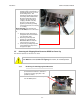
8. Tighten the hex nut to prevent the hardware
from loosening while in the un-stowed
configuration.
9. Verify that the antenna rotates freely through
its full elevation range of motion.
3.5.3. Removing the CL Shipping/Stow Restraint
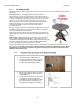
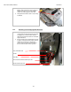
1. The CL shipping/stow restraint is formed by a
red locking bar with adjustable bumpers at
each end of the bar. This mechanism is
placed under the cross-level beam to lock it in
place.
Cross-Level Beam
CL Shipping/Stow bar
Adjustable CL Locking Bumpers (only one end shown)
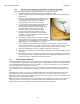
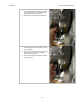
2. To un-restrain the cross-level axis of the
antenna use a 7/16“ open end wrench to
loosen the nut on the top side of the locking
bar (either end of the bar).
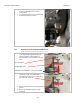
3. Remove the bottom nut off of that adjustable
bumper.
4. Remove the adjustable bumper from the
locking bar.