
Installation manual


Configuring The Satellite Modem Interface. 6012-33 Installation Manual
11-3
11.1.4. Modem I/O – Custom Settings
Use: The individual Modem I/O selections allow the user to manually define the expected driver (output) and
detector (input) circuit(s) as well as positive satellite ID
functionality between the MXP and the satellite modem.
Selection Type: Mutually Exclusive Radio Buttons
Options: Lock Input: On or Off, Polarity, 12V Pull up.
Block Output: Polarity and 12V Pull up
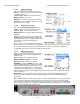
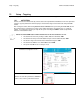
Notes: The lock input and Block output radio button
selections may only be modified if the Modem Type
“Custom” Modem Type has been selected.
If any of the other Modem Types are selected, the Lock
Input and Block Output radio buttons are predefined for
you by software and therefore become read only. This is
evidenced to the user by disabling the selections, see image to right for an example of this.
11.1.4.1. Modem I/O – Lock ON/OFF
Use: The Modem I/O Lock Input “Lock” selection defines whether or not the MXP will use positive
satellite ID functionality.
When OFF, the system will simply use the tracking receiver settings and the subsequent AGC from
the receiver to track an acquired satellite. This may be the desired satellite or it may be an adjacent
satellite that was acquired during a search for the desired satellite.
When ON, the system must get AGC and ALSO receive a network lock logic signal from the modem
to continue tracking the acquired satellite. This prevents tracking the wrong satellite and verifies
that the antenna is in fact on the desired satellite (to get network lock from the modem the antenna
must be on the correct polarity of the correct satellite). If during a search an adjacent satellite is
found, good AGC from the tracking receiver will cause the system to initially track/peak this satellite
but be waiting for a network lock signal from the satellite. If the lock signal is not received within
30-40 seconds, that system will return to the search track line and resume searching for the satellite
which provides AGC & Lock. Lock Input settings below MUST be set correctly for this functionality
to work properly.
Selection Type: Mutually Exclusive Radio Buttons
Options: Lock ON or OFF.
Notes: Modem Type “Custom” must have been selected to allow changes to these settings. Setting
Modem Lock to “ON” will enable the positive satellite ID feature whereas setting modem Lock to
“OFF” disables the feature. With the exception of the some calibration procedures (ie during Cross-
Pol isolation and 1dB compression tests) it highly recommended to leave this setting to ON. By
doing so, you eliminate tracking on adjacent satellites for any extended amount of time (typically
30-40 seconds)
11.1.4.2. Modem I/O – Lock Input – Polarity
Use: The Modem I/O Lock Input Polarity selection defines whether the hard lined wire input
provides a logic level high or logic level low as indication of Positive Satellite ID (RX Network Lock
indication).
Selection Type: Mutually Exclusive Radio Button
Options: Polarity Low or Hi.
Notes: Modem Type “Custom” must have been selected to allow changes to this setting.
You must refer to your satellite modems manufacturers written specifications for its nominal receive
lock indication output. Example if you have a satellite modem that provides a nominal 5VDC output
when in a NON-Locked condition (off satellite) and 0Vdc when in a locked condition (on satellite),
you would set Polarity to “Low”.
If your modem provides a continuity based output, short to ground is Low, and Open is High. If your
modems output is continuity based logic the Voltage must be set to 12V and the 12V pull up must
be set to “ON” (See Modem I/O Voltage & 12V Pull up sections below). Failure to do so may result in
a false Rx Lock trigger when the applicable modem interface cable is removed for any reason.