
System information


9707D-70 C-Band TXRX Installation
4-3
4.3.4.
Prepare the mounting location for the Below Decks Equipment. These equipments would normally be
installed in a standard 19” equipment rack. Refer to the Antenna Control Unit manual for installation of the
ACU and the Terminal Mounting Strip.
Preparing BDE Location
Refer to the vendor supplied manuals for installation of the other below decks equipments.
Prepare other locations throughout ship for any other equipment which is not co-located with the ACU.
4.3.5.
Install appropriate cables from Below Decks Equipment to the ADE Location(s).
Installing The System Cables
The cables must be routed from the above-decks equipment group through the deck and through various ship
spaces to the vicinity of the below-decks equipment group. When pulling the cables in place, avoid the use of
excessive force. Exercise caution during the cable installation to assure that the cables are not severely bent
(proper bend radius), kinked or twisted and that connectors are not damaged.
Assure that the cables have been run through watertight fittings and/or will not permit water entry into the
ship when the installation is completed. After cables have been routed and adjusted for correct cable length
at each end, seal the deck penetration glands and tie the cables securely in place.
4.4. Assembling the ADE
4.4.1.
Refer to the System Block diagram, General Assembly, Radome Assembly and Base frame Assembly drawings
for your system.
144” Radome, Baseframe and Antenna Pedestal System Assembly
NOTE: Unless otherwise indicated, all nuts and bolts should be assembled
with Loctite 271 or its equivalent.
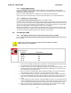
WARNING: Assure that all nut & bolt assemblies are tightened according the tightening torque
values listed below:
Bolt Size Inch Pounds
1/4-20 75
5/l6-18 132
3/8-16 236
1/2-13 517
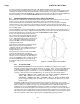
1. Select a secure assembly site that provides enough area to work with the large radome panels. Place
the radome base pan on temporary support blocks at least 22 inches high.
2. Assemble the radome base frames eight legs and eight braces using the hardware provided. Loosely
assemble all legs and braces aligning all matching marks before tightening any of the bolts. Insure
that a split washer is used under each nut.
3. Refer to the radome assembly drawing. Observe the painted numbers on the radome panels that
clearly identify their positions respective to each other and the base pan assembly.
4. Loosely assemble the 6 lower side panels, using the hardware provided, to form the bottom half of
the radome. Do NOT tighten the bolts at this time. Open each seam wide enough to install a good
bead of silicone caulk, then firmly tighten all the bolts in that flange. Repeat until all flanges are
sealed.
5. Loosely assemble the 6 upper side panels, using the hardware provided, to form the upper half of the
radome. Do NOT tighten the bolts at this time. Open each seam wide enough to install a good bead
of silicone caulk, then firmly tighten all the bolts in that flange. Repeat until all flanges are sealed.
6. Apply a good bead of silicone caulk all the way around the top cap. Install the cap into the upper
radome panel assembly using the hardware provided and tighten all the bolts.