INSTALLATION AN OPERATION FOR SEA TEL MODEL COASTAL 24 & 30 SATELLITE TV RECEIVE-ONLY ANTENNA WITH MOTORIZED POLARIZATION Please record your Antenna Serial Number Here; Antenna Size: _______ Serial Number: Sea Tel, Inc. 4030 Nelson Avenue Concord, CA 94520 Tel: (925) 798-7979 Fax: (925) 798-7986 Email: seatel@seatel.com Web: www.seatel.com August 7, 2006 _______________ Look to the Leader. Look to Sea Tel.
Sea Tel Marine Stabilized Antenna systems are manufactured in the United States of America. Sea Tel is an ISO 9001:2000 registered company. Certificate Number 19.2867 was issued August 12, 2005. Sea Tel was originally registered on November 09, 1998. The Coastal Series of Marine Stabilized Antenna Pedestals with Antenna Control Panel complied with the requirements of European Norms and European Standards EN 60945 (1997) and prETS 300 339 (1998-03) on June 30, 1999.
Revision History REV ECO# Date Description By X1 N/A July 25, 2005 Production Release MDN X2 N/A December 23, 2005 Update text to reflect changes in PCU software Rev 2.
Table of Contents 1. INTRODUCTION ................................................................................................................................. 1-1 1.1. GENERAL SYSTEM DESCRIPTION...................................................................................................... 1-1 1.2. PURPOSE ........................................................................................................................................ 1-1 1.3. SYSTEM COMPONENTS .............................
Table of Contents 4. INSTALLATION .................................................................................................................................. 4-1 4.1. SITE SELECTION AND CABLE ROUTING ............................................................................................. 4-1 4.2. EQUIPMENT AND CABLE INSTALLATION .............................................................................................. 4-2 4.2.1. Cutouts & mounting holes ......................................
Table of Contents 6.8.4. US or Aussat Linear Feed.............................................................................................. 6-11 6.9. REMOVING THE FEED ASSEMBLY & FEED TUBE .............................................................................. 6-12 6.10. REPLACE/ALIGN POLANG POT OR BELT....................................................................................... 6-14 6.11. REPLACE POLANG MOTOR OR BELT .....................................................................
Table of Contents This Page Intentionally Left Blank viii
Coastal 24 & 30 Ku-Band TVRO 1. Introduction Introduction 1.1. General System Description Your system includes a fully stabilized antenna that has been designed and manufactured so as to be inherently reliable, easy to maintain, and simple to operate. The equipment essentially permits unattended operation except for start-ups or when changing to different transponders, or satellites. 1.2.
Introduction 1.5. Coastal 24 & 30 Ku-Band TVRO Quick Overview of contents The information in this manual is organized into chapters.
Coastal 24 & 30 Ku-Band TVRO 2. Operation Operation Detailed information on operating your Coastal Series antenna from the control panel is contained below. For quick reference information, please refer to the laminated card titled “Quick Start Operation” or the previous section. 2.1. Normal Operation Flowchart The flowchart below is a quick reference from Power ON to Normal Operation Tracking a satellite. The paragraphs following this flowchart explain these phases in more detail.
Operation Coastal 24 & 30 Ku-Band TVRO 2.2.1. Power-up/Initialization Phase SEA TEL INC. SN. 98005520 COASTAL 18 INITIALIZING ✴ Second line will display the antenna pedestal serial number that has been saved in the Pedestal Control Unit (PCU), for a few seconds. The Model number that has been saved in the PCU will be displayed on the top line. “INITIALIZING” followed by a “o” until the GPS has a valid position. When the GPS has a valid position “INITIALIZING ✴” is displayed. 2.2.2.
Coastal 24 & 30 Ku-Band TVRO 4 Operation Search Next DN - Will be displayed whenever the system conducts a search for the next satellite DOWN (CCW/Left) from the satellite location it was previously at. This search may be initiated automatically or when the operator presses the NEXT key. 2.2.3. Tracking phase Sat1 DTV101 1876 1 NID FFFE EL 45 First line of the TRACKING display will be the information for the satellite which is currently being tracked.
Operation 2.5. Coastal 24 & 30 Ku-Band TVRO Loss of satellite due to blockage or rain-fade If tracking is lost due to blockage or rain fade, the antenna will search until a signal is found which is high enough for the antenna to begin tracking. When the receiver interface is operating properly, the antenna will automatically continue searching until it has acquired the desired satellite. 2.6. Low Noise Block Converter Operation There are no operating instructions or controls applicable to the LNB.
Coastal 24 & 30 Ku-Band TVRO 3. Basic System Information Basic System Information This section provides you with some additional information about the satellites you will be using, basics of the your antenna system and other equipment within your system configuration. 3.1. Satellite Basics The Television Receive Only (TVRO) satellites are in orbit at an altitude of 22,753.2 Miles (36,600 kilometers) and positioned directly above the equator.
Basic System Information Coastal 24 & 30 Ku-Band TVRO system must be geographically located in an area where the satellite signal level is high enough to provide suitable reception. This limits the number of satellites that can be used and the geographic areas where the boat can travel where the signal level is expected to be strong enough to continue providing uninterrupted reception.
Coastal 24 & 30 Ku-Band TVRO Basic System Information Both horizontal and vertical signals from a satellite will appear to be rotated the same amount and are always perpendicular to each other. The amount of rotation is dependent on how far east or west the satellite is from you and how close you are to the Equator (refer to the polarization information in the Setup and the Operation sections of this manual). 3.2.
Basic System Information Coastal 24 & 30 Ku-Band TVRO 3.2.4. Stabilization Your antenna is a “stabilized” antenna. Stabilization is the process of de-coupling the ships’ motion from the antenna. Simply put, this allows the antenna to remain pointed at the satellite while the boat turns, rolls or pitches under it. To accomplish this, the Pedestal Control Unit (PCU) on the antenna pedestal assembly senses the motion and applies drive to the appropriate motor(s) in opposition to the sensed motion.
Coastal 24 & 30 Ku-Band TVRO 3.3. Basic System Information Components of the System Configuration The following text provides a basic functional overview of the system components and component interconnection as referred to in the System Block Diagram for your model antenna (refer to the appropriate page which depicts your system configuration).
Basic System Information Coastal 24 & 30 Ku-Band TVRO 3.3.3. Power Supply DC Voltage - Power for the antenna is taken directly from the vessel’s 12 volt DC system for maximum power efficiency. At 13.8VDC the nominal current drain required by the antenna is 3.0 Amps. AC Voltage - An appropriate source of AC Voltage will also be required for the active matrix switch, satellite receivers and television monitors. Refer to the manuals for these devices for voltage and power consumption of each.
Coastal 24 & 30 Ku-Band TVRO 4. Installation Installation Installation of your Coastal Series Antenna system must be accomplished by or under the supervision of an authorized Sea Tel dealer for the Sea Tel Limited Warranty to be valid and in force. Good planning of the installation will provide the best results. Below is some guidance on issues that are important to consider when planning the installation. Planning is the key to a good installation.
Installation Coastal 24 & 30 Ku-Band TVRO Satellite receiver(s) and television set(s) - Satellite receiver(s) and television set(s) should be mounted near each other in convenient viewing locations. If enclosed in a cabinet or panel, assure that there is adequate airflow to prevent the receiver from over-heating and provide forced airflow if needed.
Coastal 24 & 30 Ku-Band TVRO Installation 4.2.1. Cutouts & mounting holes 1 Using the radome template portion of drawing 118092 for Coastal 18 or 24, or 125369 for the Coastal 30, mark the mounting holes and cable passage cutout. Drill the mounting holes for the radome. A hole saw may be used to cut out the cable passage (for routing the cables into the base of the radome).
Installation Coastal 24 & 30 Ku-Band TVRO 4.2.3. Radome Mounting and antenna cable connections 2 Refer to the Installation Arrangement drawing. Remove the radome top by removing the four cap nuts from the bolts that thread up into the recess areas of the radome base. Set the radome top and cap nuts aside for later re-use. 3 Remove the 3/8-16 hex jam nuts and washers (four places) from the under-side of the radome base. Gently lift the antenna pedestal assembly out of the radome base.
Coastal 24 & 30 Ku-Band TVRO Installation 7 Apply Loctite 241 (supplied) to the outer threads of the threaded insert and install the 3/8 washers and 3/8-16 hex jam nuts to the four threaded inserts. This mounts the Pedestal Assembly inside the radome base. 8 Apply Loctite 241 (supplied) to the top of the four ¼” diameter x 4” long mounting studs and install the studs up into the threaded inserts in the antenna pedestal assembly from the underside of the radome base.
Installation Coastal 24 & 30 Ku-Band TVRO 10 Install a ¼” fender washer and nut to each mounting stud from the underside of the mounting surface. 11 Apply Loctite 241 (supplied) to the threads of the mounting stud up near the mounting surface and tighten each of the 4 nuts to 24 in-lb (21 kg-cm) torque [finger tight, then about ¼ turn tighter] with a wrench. DO NOT OVER TIGHTEN. 12 If desired, the remaining length of threaded rod that extends below the nut may be cut off.
Coastal 24 & 30 Ku-Band TVRO Installation 4.2.4. Other system cable connections 1 Connect the 8-pin screw terminal connector on the control cable to J2 on the back of the antenna control panel. Leave sufficient length on the cable connections to the antenna control panel to be able to remove it for testing or replacement. Excess control cable length below decks may be cut off and re-terminated according to the detail on the System Block Diagram, if necessary.
Installation Coastal 24 & 30 Ku-Band TVRO This Page Intentionally Left Blank 4-8
Coastal 24 & 30 Ku-Band TVRO 5. Setup Setup 5.1. 5.2. System Checkout 1 Press the ON key on the antenna control panel. Both LED’s (TRACKING and UNWRAP) should illuminate for 5 seconds verifying the DC power and LED cable connections between the antenna control panel and the antenna pedestal assembly. 2 Turn power ON to the satellite receiver and the TV monitor.
Setup Coastal 24 & 30 Ku-Band TVRO arrow keys to increment/decrement the indicated character to the desired value. 4 Repeat the previous step until all desired character positions have been edited. 5 Then press the SAVE key once to save this setting. 6 Press the ▼ arrow key to go to the next parameter. 5.2.3. SAT1 - First Satellite Parameters Access all of the SAT1 individual parameters via a sub menu. Choices are: 5.2.3.1.
Coastal 24 & 30 Ku-Band TVRO Setup increment/decrement this character. 8 Press the NEXT key to move the cursor to the next character to the right. Press ▲ & ▼ arrow keys to increment/decrement this character. 9 Continue editing characters (6 max) until all desired characters have been set to create the NAME you want to use for this satellite selection. Press the SAVE key to save the NAME parameter for this SAT.
Setup Coastal 24 & 30 Ku-Band TVRO 5.2.3.5.ALTFREQ For future use. Set to 0000. 5.2.3.6.BAUD Enter or edit the best Baud rate for the receiver to use for this satellite. Range of acceptable input is 5000-30000 symbols per second. 1 Press the NEXT key to SELECT this sub-menu parameter for adjustment. 2 A cursor will appear under the rightmost digit. Press ▲ & ▼ arrow keys to increment/decrement this digit. 3 Press the NEXT key to move the cursor to the digit to the left.
Coastal 24 & 30 Ku-Band TVRO 3/4* 5/6* 6/7* 7/8* NBIF Setup SCPC mode may be selected for tracking narrow band signals. This is not normally needed for tracking satellite TV signals. 3 When the desired choice is displayed, press the SAVE key to save the parameters for this SAT. This saves the FEC rate to use for this SAT. 4 If you want to edit any of the default values that are loaded with preset, press the ▼ arrow key to go to the next sub-menu parameter.
Setup Coastal 24 & 30 Ku-Band TVRO 4 If you want to edit any of the other default values that are loaded with preset, press the ▼ arrow key to go to the next sub-menu parameter. 5 If you do not want to edit any other sub-menu parameters, press SAVE again to exit the submenu and return to the SAT main menu display. From there you can press the ▼ arrow key to go to next SAT numeric menu choice or to the Factory Settings menu choice. 5.2.4.
Coastal 24 & 30 Ku-Band TVRO Setup 5.2.9. FACTORY SETTINGS Accessing the Factory Settings parameters should ONLY be done by a qualified technician from an authorized Sea Tel dealer. The Model Serial Number can be found on the blue and silver label below the reflector, on the blue frame of the pedestal. The parameters are: 5.2.9.1.MODEL COASTAL ## This parameter sets all of the internal drive, scale factor and limits for the motors, gear ratios and sensors FOR THIS MODEL ANTENNA.
Setup Coastal 24 & 30 Ku-Band TVRO increment/decrement this digit. 5.3. 4 Continue editing until all 6 digits have been set to the correct Serial Number of the antenna pedestal that this PCU is mounted on. Press the SAVE key to save the Serial Number parameter. 5 Press SAVE again to exit the sub-menu and return to the FACTORY SETTINGS main menu display. From there you can press the ▲ arrow key to go UP through the SAT numeric menu choices.
Coastal 24 & 30 Ku-Band TVRO Setup opposite direction to increase the signal strength. 4 When the polarization of the antenna is optimum, press and hold the SAVE key for 6 seconds to save the optimized polarization setting value to the POL TRIM parameter for this selected satellite (SAT1-SAT6). Select another satellite which you have set-up and optimize the polarization of that satellite using steps 14. Repeat until all of the your desired satellites have been optimized. 5.4.
Setup Coastal 24 & 30 Ku-Band TVRO Figure 5-2 Display Antenna Control Panel – Setup Mode, page 1 5-10
Coastal 24 & 30 Ku-Band TVRO Setup Figure 5-3 Display Antenna Control Panel – Setup Mode, page 2 5-11
Setup Coastal 24 & 30 Ku-Band TVRO Figure 5-4 Display Antenna Control Panel – Setup Mode, page 3 5-12
Coastal 24 & 30 Ku-Band TVRO Setup Figure 5-5 Display Antenna Control Panel – Setup Mode, page 4 5-13
Setup Coastal 24 & 30 Ku-Band TVRO Figure 5-6 Display Antenna Control Panel – Setup Mode, page 5 5-14
Coastal 24 & 30 Ku-Band TVRO 6. Maintenance Maintenance 6.1. Warranty Information Sea Tel Inc. supports its Coastal Series systems with a warranty program unsurpassed in the industry. These systems are backed by a TWO YEAR full warranty on parts and a ONE YEAR warranty on labor.
Maintenance 6.3. Coastal 24 & 30 Ku-Band TVRO Preventive Maintenance As needed - Clean the outside surface of the radome with warm soapy water to remove dust, grime and salt residue. There is no other preventive maintenance required 6.4. Fault Isolation/Trouble-shooting The following table is provided to help isolate problems in the Series Antenna system. Symptom Possible Fault Antenna tracking but receiver not providing desired programming 1. Incorrect satellite.
Coastal 24 & 30 Ku-Band TVRO Antenna does not come on when the ON key is pressed Maintenance 1. Check +12 VDC input to antenna control panel. 2. Verify that all connections on the rear of the antenna control panel are properly seated. 3. Check the 4A fuse in the rear panel of the antenna control panel 4. Call dealer/agent for further assistance Antenna doesn’t track any satellites 1. Assure that at least one receiver is ON (constantly searching) 2. Check for blockage 3.
Maintenance Coastal 24 & 30 Ku-Band TVRO To access the BIT function, turn the antenna system Power OFF at the Display Antenna Control Panel (DACP). While you Press & Hold the NEXT key, press the POWER key. After a few seconds, you will see “Built In Test” on the top line of the display and “Press Next to begin” on the second line. Press NEXT and the BIT tests will begin and run automatically until completed (“BIT Finished No Errors” will be displayed) or until a test fails. The BIT tests are: 6.5.1.
Coastal 24 & 30 Ku-Band TVRO Maintenance 6.5.5. POL Motor Driver Test This test checks the ability of the motor driver to drive current through the Polarization motor. The current to the motor is controlled by a PWM circuit. The PWM current is repeatedly sampled and statistically analyzed during this test. “Testing POL MTR” will be displayed as the test runs. An Error code 5.01-5.17 will be displayed if one of these tests fails. A failure indicates a failed motor, Motor Driver PCB or harness.
Maintenance Coastal 24 & 30 Ku-Band TVRO 6.5.8. Pol Pot/Motor move test This test moves the feed assembly at various speeds in Polarization and checks the results using the POL potentiometer. “Test POL Assy” will be displayed as the test runs. An Error code 8.01-8.07 will be displayed if one of these tests fails. A failure indicates a failed motor, belt or potentiometer. This could be due to: • Mechanical binding of the polarization assembly.
Coastal 24 & 30 Ku-Band TVRO 6.6. Maintenance Replacing a Defective LNB Follow the procedure below to install and align a replacement LNB. After the LNB is installed, the POL OFFSET parameter must be re-optimized. 1 Adjust the Polarization setting in the Antenna Control Panel to read 090. The Polarization Motor will rotate the current LNB to a vertical position (straight up). 2 Turn power OFF at the Antenna Control Panel. 3 Remove radome top.
Maintenance Coastal 24 & 30 Ku-Band TVRO 10 Turn antenna power ON at the Antenna Control Unit. 11 If you replaced a linear LNB, re-optimize the polarization (refer to section 5.3). 12 Verify that the LNB operating properly and resume normal operation. 6.7. Changing to a different LNB The Coastal Series antennas can be easily fitted with a variety of LNB assemblies.
Coastal 24 & 30 Ku-Band TVRO Maintenance 5 Loosen the Allen set screws on the existing LNB mounting collar (three set screws, 120 degrees apart) and remove it from the mounting collar. NOTE: You may need to loosen the four screws that attach the mounting collar to the driven gear and remove the LNB and mounting collar.
Maintenance Coastal 24 & 30 Ku-Band TVRO 6.8.1. US or DLA Circular Feed 1 The counterweight bracket must be inverted (mounted from the under-side of the feed plate with the strengthener ribs UP toward the LNB, away from the dish). 2 Mount a total of 7 ½ oz of counter weight in the left hole on the counterweight bracket. 3 Mount a total of 3 oz of counter weight in the right hole on the counterweight bracket. 4 Mount a total of 9 oz of counter weight in the hole on the left side of the feed plate.
Coastal 24 & 30 Ku-Band TVRO Maintenance 6.8.3. Quad Linear Feed 1 The counterweight bracket must be mounted from the upper-side of the feed plate with the strengthener ribs DOWN toward the dish. 2 Mount a total of 7 ½ oz of counter weight in the left hole on the counterweight bracket. 3 Mount a total of 1 oz of counter weight in the hole on the right side of the feed plate. 4 Return to LNB installation procedure. Quad Linear Feed Assembly Balancing 6.8.4.
Maintenance 6.9. Coastal 24 & 30 Ku-Band TVRO Removing the Feed Assembly & Feed Tube It may be easier to change the balancing weight configuration with the feed assembly removed from the dish and will prevent unintentional scratching or damaging of the back of the dish. You will also have to remove the Feed Assembly & Feed Tube to replace or repair either of these components. 1 Loosen the 4 Allen set screws that mount the Feed Tube and the Feed Assembly to the dish.
Coastal 24 & 30 Ku-Band TVRO 4 Repair Feed assembly (refer to Polang Pot or Pot Belt alignment OR Polang Motor or Polang Belt alignment procedures below). 5 Assure that you align the phase card inside the Feed Tube to be VERTICAL (relative to the top and bottom of the dish) when you remount the Feed tube to the dish. 6 Insert one of the set screws through the Feed Tube (phase card vertical), through the dish and thread it into the Feed Assembly (polang Motor down).
Maintenance Coastal 24 & 30 Ku-Band TVRO 6.10. Replace/Align Polang Pot or Belt If the Polang Pot or Belt becomes loose or fails, you will have to remove the Feed Assembly to repair and realign it to restore normal operation. 1 Remove the Feed Assembly (refer to paragraph 6.9 above). 2 If the Polang Pot has failed, go to step 5. 3 If the belt is broken, skip to step 11. 4 If the belt has slipped and the pot is only out of alignment, skip to step 11.
Coastal 24 & 30 Ku-Band TVRO Maintenance 13 Check the belt tension by pinching both sides of the belt. The belt should depress about 1/16” on both sides with light finger pressure. 14 Rotate the LNB, and the large sprocket, to vertical position. This should align the marks on the large sprocket (on the back of the feed assembly) to be lined up with the shaft of the Pot.
Maintenance Coastal 24 & 30 Ku-Band TVRO 17 If the Pot was NOT replaced skip to step 22. 18 If the pot WAS replaced, hold the sprockets in alignment and use a flat blade screwdriver to rotate the shaft of the Pot to one end stop of the Pot. The Pot is has a 3 turn range from one stop to the other. From one stop, rotate the shaft 1 ½ turns to center of the Pots’ range. This sets the center of the pot to be in-line with the center of the mechanical range of rotation of the large sprocket.
Coastal 24 & 30 Ku-Band TVRO Maintenance 22 Rotate the large sprocket full CCW. The timing mark on the pot sprocket should be inside the right side of the belt as shown. 23 The distance from the timing mark on the Pot sprocket to the belt should be same from both ends (CW & CCW). If they are not repeat step 15 and re-evaluate CW & CCW rotations. 24 Re-install the Feed Tube and Feed Assembly as described in paragraph 6.9 above.
Maintenance Coastal 24 & 30 Ku-Band TVRO 6.11. Replace Polang Motor or Belt If the Polang Motor or Belt fails, you will have to remove the Feed Assembly to repair and re-align the Polang Pot to restore normal operation. 1 Remove the Feed Assembly (refer to paragraph 6.9 above). 2 If the Motor has failed, skip to step 4. 3 If the belt has broken, skip to step 8. 4 Remove the motor 3 mounting set screws. Each of the set screws has a hex nut in a slot on the under-side of the feed plate.
Coastal 24 & 30 Ku-Band TVRO Maintenance 12 Check the belt tension by pinching both sides of the belt. The belt should depress about 1/16” on both sides with light finger pressure. Adjust motor mounting if belt tension is too loose or too tight. 13 Re-install the Feed Tube and Feed Assembly as described in paragraph 6.9 above. 14 Re-attach the coax cables to the LNB, assure that the correct color coax is attached to the correct port on the LNB.
Maintenance Coastal 24 & 30 Ku-Band TVRO This Page Intentionally Left Blank 6-20
Coastal 24 & 30 Ku-Band TVRO 7. Coastal 24 & 30 Technical Specifications Coastal 24 & 30 Technical Specifications 7.1. Installed Weight Total Weight (dry): Coastal 24 48 lbs. (21.8 kg) Coastal 30 112 lbs. (50.8 kg) *NOTE: 34” Radome panels can absorb up to 50% moisture by weight. 7.2. Radome Diameter Height Mounting Wind: Coastal 24 Coastal 30 27 inch (68.9cm) 37.7 inch (95.8cm) 26.5 inch (67.3cm) 39.6 inch (100.6cm) 4 x ¼-20 fasteners equally spaced on 12.73” D.B.C.
Coastal 24 & 30 Technical Specifications Coastal 24 & 30 Ku-Band TVRO 7.4.2. KoreaSat Circular LNB Sea Tel Part Number: Type: LNB Manufacturer: RF Frequencies: IF Frequency: LO Frequency: Noise Figure: Polarization modes: Polarization control: 116910-1 Single output HET, but may vary 11.7 - 12.75 GHz 950 - 2000 MHz 11.750 GHz 0.8 dB max. LHCP circular 18 VDC 7.4.3.
Coastal 24 & 30 Ku-Band TVRO Coastal 24 & 30 Technical Specifications 7.4.6. US Linear LNB Sea Tel Part Number: Type: LNB Manufacturer: RF Frequencies: IF Frequency: LO Frequency: Noise Figure: Polarization modes: Polarization control: 118740 Dual output Zinwell, but may vary 11.7 - 12.2 GHz 950 - 1450 MHz 10.75 GHz 0.9 dB max. Horizontal or Vertical Linear 18VDC (H) or 13VDC (V) voltage switched 7.4.7.
Coastal 24 & 30 Technical Specifications Elevation Pointing +/- 0 degrees of Roll +/- 15 degrees of Roll +/- 25 degrees of Roll 7.6. Coastal 24 & 30 Ku-Band TVRO Coastal 18, 24 & 30 = 15 to 70 degrees Coastal 18 & 24 = 25 to 60 degrees Coastal 30 = 20 to 60 degrees Coastal 18 & 24 = 35 to 50 degrees Coastal 30 = 30 to 50 degrees Pedestal Control Unit Size Features Connectors Below Decks Interface Elevation/Azimuth Motors RF Signal Monitor 5 x 11 x 1.2 inches (12.7 x 27.9 x 3.
Coastal 24 & 30 Ku-Band TVRO 7.8. Power Requirements Voltage Current Transient Protection Load Dump Inductive coupling Reverse Battery 24V Jump Start 7.9. Coastal 24 & 30 Technical Specifications 11-16 VDC normal operating range 3.0 Amps nominal @ 13.8 VDC 60 volts +/- 200v @ 1 uSec Indefinite 1 minute Environmental Temperature Humidity Rain -20 to +55 degrees C. Up to l00% @ 40 degrees C. Up to 4 inches per hour. Degraded RF performance when the radome surface is wet.
Coastal 24 & 30 Ku-Band TVRO 8. Computer Interface Computer Interface A computer can be connected to the antenna control panel to allow you to provide access to ALL the parameter settings of the query the Coastal Series antenna and view the responses it provides. The commands to set the parameters in the Coastal Series PCU are summarized below. Changing the parameters for the primary and secondary satellites may be easily done using the computer interface.
Computer Interface Coastal 24 & 30 Ku-Band TVRO 7 Check “Send line ends with line feeds”, “Echo typed characters locally” and “Append line feeds to incoming line ends”. Click OK. 8 Type ^0086 and hit ENTER. 9 Refer to the command information below to communicate with the antenna system. The Display Antenna Control Panel will be locked while you are connected to the computer. 10 When you are finished, close the terminal program and disconnect the computer from the Display Antenna Control Panel.
Coastal 24 & 30 Ku-Band TVRO Computer Interface Control Function ^0080↵ Start bootloader. ^0086↵ Disable DACP updates and enter diagnostic test mode. ^0090↵ Reboot PCU. edddd↵ Set elevation target to ddd.d degrees. jdddd↵ Set pseudo azimuth target to ddd.d degrees. mnn↵ Set Model type to nn (range 18, 24, 30). pnnn↵ Set POLANG target to nnn degrees (range, 20 to 160, nominal setting of 90). tnnnn↵ Set THRESHOLD to nnnn counts (0-4095).
Computer Interface Coastal 24 & 30 Ku-Band TVRO This page left blank intentionally 8-4
Coastal 24 & 30 Ku-Band TVRO 9. Drawings DRAWINGS The following drawings are included with this manual for installation and maintenance reference.
Drawings Coastal 24 & 30 Ku-Band TVRO This page left blank intentionally 9-2
COASTAL SERIES SYSTEM CONFIGURATOR CHART System Description Coastal 18, EU Coastal 18, Aussat Coastal 18, US Linear Coastal 18, Euro Quad Coastal 18, DBS Coastal 18, Korea-Sat Coastal 18, DLA Coastal 18, Americas Coastal 24, EU Coastal 24, Aussat Coastal 24, US Linear Coastal 24, Euro Quad Coastal 24, DBS Coastal 24, Korea-Sat Coastal 24, DLA Coastal 24, Americas Coastal 30, EU Coastal 30, Aussat Coastal 30, US Linear Coastal 30, Euroquad Coastal 30, DBS Coastal 30, Korea-Sat Coastal 30, DLA Coastal 30,
SINGLE LEVEL MFG BILL OF MATERIAL FIND QTY PART NO REV DESCRIPTION REFERENCE DESIGNATOR 1 1 EA 123706-1 D GENERAL ASS'Y, COASTAL 24, MOTORIZE 2 1 EA 123705-1 X3 ANTENNA ASS'Y, COASTAL 24, MOTORIZE 3 0 EA COMMENTS 4 1 EA 121229 5 1 EA 117043-5 X1 HARNESS ASS'Y, INTERFACE 6 1 EA 119205 A BRACKET, CONNECTOR, ADAPTER 7 2 EA 114178 O ADAPTER, F(F)-F(F) (BULLET), 1.
SINGLE LEVEL MFG BILL OF MATERIAL FIND QTY PART NO REV DESCRIPTION REFERENCE DESIGNATOR 1 1 EA 123813-1 D GENERAL ASS'Y, COASTAL 30, W/AUTO P 2 1 EA 123701-1 X3 ANTENNA ASS'Y, COASTAL 30, W/AUTO P 3 0 EA COMMENTS 4 1 EA 121229 5 1 EA 117043-5 X1 HARNESS ASS'Y, INTERFACE 6 1 EA 119205 A BRACKET, CONNECTOR, ADAPTER 7 2 EA 114178 O ADAPTER, F(F)-F(F) (BULLET), 1.
SINGLE LEVEL MFG BILL OF MATERIAL FIND QTY PART NO REV DESCRIPTION REFERENCE DESIGNATOR 0 EA 124869 2.05h SOFTWARE, COASTAL PCU 1 1 EA 123709 G PEDESTAL ASS'Y, COASTAL 24 2 1 EA 123705-1 X3 ANTENNA ASS'Y, COASTAL 24, MOTORIZE 4 1 EA 121966-4 B GPS ANTENNA, RETERMINATED, 72.
8 6 7 5 4 2 3 1 REVISION HISTORY NOTES: UNLESS OTHERWISE SPECIFIED 1. APPLY ADHESIVE PER SEATEL SPEC. 121730. D 2. TORQUE THREADED FASTENERS PER SEATEL SPEC. 122305. 3. 4 ROUTE ALL HARNESS AND CABLES ASSEMBLIES PER SEATEL SPEC. 121872. CONNECT CABLE ASS'Y MOTOR, DRIVE P/N 124902, P/O POLANG ASSEMBLY, TO THIS CONNECTOR. 5 TERMINATE ALL UNUSED COAX CONNECTORS. REFERENCE DRAWINGS: 124665 SYSTEM BLOCK DIAGRAM. 124735 ANTENNA SYSTEM SCHEMATIC. 124736 INSTALLATION ARRANGEMENT.
SINGLE LEVEL MFG BILL OF MATERIAL FIND QTY PART NO REV DESCRIPTION REFERENCE DESIGNATOR 0 EA 124869 2.05h SOFTWARE, COASTAL PCU 1 EA 117164-30 A2 CABLE ASS'Y, RG-179 COAX, F TO F, 30 IN NOT SHOWN IN DWG (SEE REF 1 1 EA 124365-1 B PEDESTAL ASS'Y, COASTAL 30 2 1 EA 123701-1 X3 ANTENNA ASS'Y, COASTAL 30, W/AUTO P 3 1 EA 121966-4 B GPS ANTENNA, RETERMINATED, 72.
8 6 7 5 4 2 3 1 REVISION HISTORY REFERENCE DRAWINGS 124665 SYSTEM BLOCK DIAGRAM. 124736 G.A. INSTALLATION ARRANGEMENT. 124050 WEIGHT CONFIGURATION KIT. 125011 HARNESS ROUTING DOC. NOTES: UNLESS OTHERWISE SPECIFIED 1. APPLY ADHESIVE PER SEATEL SPEC. 121730. 2. TORQUE THREADED FASTENERS PER SEATEL SPEC. 122305. D CL 3. TENSION ALL BELTS PER SEATEL SPEC. 122319.
SINGLE LEVEL MFG BILL OF MATERIAL FIND QTY PART NO REV DESCRIPTION REFERENCE DESIGNATOR 1 1 EA 124502-2 B BASE SPINDLE/YOKE ASS'Y, COASTAL 24 2 1 EA 123707 B ELEVATION ASS'Y, 2498S & 2498SE 3 1 EA 121229 L PCU ENCLOSURE ASS'Y, 2-AXIS 4 1 EA 110873-3 D RF SPLITTER 5 1 EA 112573-2 B TRIM WEIGHT, 1.17 LBS 6 1 EA 124468 A BRACKET, PCU 10 8 EA 114588-192 SCREW, PAN HD, PHIL, 8-32 x 3/8, S.S. 11 2 EA 114588-199 SCREW, PAN HD, PHIL, 8-32 x 1, S.S.
8 6 7 5 4 2 3 1 REVISION HISTORY NOTES: UNLESS OTHERWISE SPECIFIED 1. APPLY ADHESIVE PER SEATEL SPEC. 121730. REV ECO# DATE D 5042 10-18-05 2. TORQUE THREADED FASTENERS PER SEATEL SPEC. 122305. D DESCRIPTION BY ADDED CT WEIGHT P/N 118560; CHANGED ITEM 24 P/N FROM 123082-1111 TO 123082-1051 AEF ITEM 13 P/N WS 114586-540; ITEM 23 P/N WS 114593-122 3. TENSION ALL BELTS PER SEATEL SPEC. 122319.
SINGLE LEVEL MFG BILL OF MATERIAL FIND QTY PART NO REV DESCRIPTION REFERENCE DESIGNATOR 1 1 EA 124223-1 B BASE SPINDLE ASS'Y, COASTAL 30 2 1 EA 121478 C ELEVATION ASS'Y, 3098S, 3098SE 3 1 EA 121229 L PCU ENCLOSURE ASS'Y, 2-AXIS 4 1 EA 110873-3 D RF SPLITTER 5 1 EA 112573-2 B TRIM WEIGHT, 1.17 LBS 6 1 EA 124468 A BRACKET, PCU 11 4 EA 114588-194 SCREW, PAN HD, PHIL, 8-32 x 1/2, S.S. 12 4 EA 114588-190 SCREW, PAN HD, PHIL, 8-32 x 1/4, S.S.
8 6 7 5 4 2 3 1 REVISION HISTORY NOTES: UNLESS OTHERWISE SPECIFIED 1. APPLY ADHESIVE PER SEATEL SPEC. 121730. 2. TORQUE THREADED FASTENERS PER SEATEL SPEC. 122305. D 3. TENSION ALL BELTS PER SEATEL SPEC. 122319. 2X 2X ECO# DATE A 5098 02-16-06 RELEASED TO PRODUCTION, WAS X3, REMOVED ITEMS 8 - 10, 17, REPLACED ITEMS 16 & 20, ADDED ITEMS 21 - 24 K.D.H. A1 N/A 03-16-06 ADDED ITEM 16, ITEM 11 WAS 12, ITEM 22 WAS 13; (BUBBLE CHG ON DWG ONLY - NO BOM) K.D.H.
SINGLE LEVEL MFG BILL OF MATERIAL FIND QTY PART NO REV DESCRIPTION REFERENCE DESIGNATOR 1 1 EA 123741 X1 REFLECTOR, 24 IN, MACHINING 2 1 EA 123700-1 X7 POLANG ASS'Y, COASTAL SERIES 3 1 EA 122096 B RETAINER, LNB 4 1 EA 124828-1 VERTEX FEED, 24 IN DBS 50 4 EA 114593-104 SCREW, SOCKET HD, 4-40 x 3/8, S.S. 51 8 EA 114580-005 WASHER, FLAT, #4, S.S. 52 3 EA 114590-188 SCREW, SOCKET SET-CUP, 8-32 x 1/8, S.S 53 4 EA 114593-106 SCREW, SOCKET HD, 4-40 x 1/2, S.S.
8 7 6 5 4 2 3 1 REVISION HISTORY DASH # NOTES: UNLESS OTHERWISE SPECIFIED 1. APPLY ADHESIVE PER SEATEL SPEC. 121730. DESCRIPTION SHEET # -1 ANTENNA ASSEMBLY W/AUTO POL. 1 -2 ANTENNA ASSEMBLY W/O AUTO POL. 2 REV ECO# DATE X3 5030 10-18-05 DESCRIPTION BY REPLACED VERTEX FEED P/N FROM 123141 TO 124828-1 AEF 2. TORQUE THREADED FASTENERS PER SEATEL SPEC. 122305. D D 4 1 PLACE VERTEX FEED TUBE WITH PHASE CARD IN ORIENTATION SHOWN.
8 6 7 5 4 2 3 1 D D C C B 5 B 4X 1 6 4X 2 3 4 3X PLACE VERTEX FEED TUBE WITH PHASE CARD IN ORIENTATION SHOWN. A A VIEW IS FROM VERTEX TUBE SIDE.
SINGLE LEVEL MFG BILL OF MATERIAL FIND QTY PART NO REV DESCRIPTION REFERENCE DESIGNATOR 1 1 EA 122180 B1 REFLECTOR MACHINING, 30 IN. RX ONLY 2 1 EA 123700-1 X7 POLANG ASS'Y, COASTAL SERIES 4 1 EA 124829-1 5 1 EA 122096 51 4 EA 114580-005 WASHER, FLAT, #4, S.S. 53 4 EA 114593-106 SCREW, SOCKET HD, 4-40 x 1/2, S.S. 54 4 EA 114581-005 WASHER, LOCK, #4, S.S. 55 3 EA 114580-008 WASHER, FLAT, #6, SMALL PATTERN, S.S.
8 7 6 5 4 2 3 1 REVISION HISTORY NOTES: UNLESS OTHERWISE SPECIFIED 1. APPLY ADHESIVE PER SEATEL SPEC. 121730. D 2. TORQUE THREADED FASTENERS PER SEATEL SPEC. 122305. 3. SEE SHEET 2 FOR POLANG ASSEMBLY ORIENTATION. DESCRIPTION REV ECO# DATE BY X2 4963 08-26-05 SHEET TWO ADDED, DASH TABLE ADDED AEF X3 5030 10-19-05 REMOVED ITEM 3 FROM BOM & DWG; ITEM 4 CHANGED P/N FROM 123141 TO 124829-1.
8 6 7 5 4 2 3 1 1 2 D D C C 4X 54 4X 51 4X 52 4 B 55 B 3X -2 ANTENNA ASSEMBLY PLACE VERTEX FEED WITH PHASE CARD ORIENTATION SHOWN. (BOTH ANTENNA ASSEMBLIES). A A ORIENT POLANG STOPS PER DETAIL VIEW. POLANG ASS'Y, MOUNTING DETAIL VIEW IS FROM VERTEX TUBE SIDE.
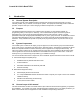
8 6 7 5 4 2 3 1 REVISION HISTORY DESCRIPTION BY REV ECO# DATE X1 5147 03-15-06 NEW ASSEMBLY DRAWING K.D.H. X2 N/A 03-24-06 ITEM 52 WAS P/N 114586-540, NOW IS 114586-538, CHANGED NOTE IN ZONE A-7 FROM "1/2-13 X 1 1/4 HEX SCREW" TO "1/2-13 X 1 HEX SCREW", CORRESPONDS TO ITEM 50 ON BOM K.D.H. X3 N/A 03-31-06 ITEM 12 WAS P/N 110481-3, NOW IS 110481-4 K.D.H 12X 52 24X 53 D 1 D 12X 54 9.7 DETAIL B SCALE 1 : 1.5 3 39.6 MAX 4X .56 (CLEARANCE FOR 1/2-13 FASTENERS) C 9.7 C 13.
8 6 7 5 4 D 50 4X 55 56 4X 57 58 61 62 4X 51 2 3 1 6 4X 4X 5 4X 7 4X 8 D 9 C C 4X 10 6" HOLE FOR CABLE ROUTING. C B B ANTENNA CONTROL PANEL, SEE BELOW FOR MOUNTING PATTERN C (GRN) HI-VERTICAL A (RED) HI-HORIZONTAL D (BLU) LO-VERTICAL A 4X .14 (CLEARANCE FOR #6 SHEET METAL SCREW) B (WHT) LO-HORIZONTAL 4 2X 4 2.70 15 DETAIL C SCALE 1 : 2 CONTROL CABLE CONNECTS HERE, CONNECTOR NOT SHOWN. 3X 8 7 59 .110 .145 4.91 5.20 60 6 2.
SHIELDED CONTROL CABLE ASSEMBLY 117230 C2