INSTALLATION AND MAINTENANCE MANUAL FOR SEA TEL MODEL COASTAL 14E SATELLITE TV RECEIVE-ONLY ANTENNA Sea Tel, Inc. 4030 Nelson Avenue Concord, CA 94520 Tel: (925) 798-7979 Fax: (925) 798-7986 Email: seatel@seatel.com Web: www.seatel.com November 6, 2007 Look to the Leader. Look to Sea Tel. Sea Tel Europe Unit 1, Orion Industrial Centre Wide Lane, Swaythling Southampton, UK S0 18 2HJ Tel: 44 (0)23 80 671155 Fax: 44 (0)23 80 671166 Email: europe@seatel.com Web: www.seatel.com Document. No.
Sea Tel Marine Stabilized Antenna systems are manufactured in the United States of America. Sea Tel is an ISO 9001:2000 registered company. Certificate Number 19.2867 was issued August 12, 2005. Sea Tel was originally registered on November 09, 1998. Copyright Notice All Rights Reserved. The information contained in this document is proprietary to Sea Tel, Inc.. This document may not be reproduced or distributed in any form without the consent of Sea Tel, Inc.
Table of Contents 1. INSTALLATION .................................................................................................................................. 1-1 1.1. SITE SELECTION AND CABLE ROUTING PATH .................................................................................... 1-1 1.2. COASTAL 14E SYSTEM INVENTORY ................................................................................................. 1-2 1.3. REQUIRED TOOLS ..................................................
Table of Contents 4.7. POWER REQUIREMENTS ................................................................................................................ 4-3 4.8. ENVIRONMENTAL .......................................................................................................................... 4-3 4.9. ANTENNA CONTROL PANEL ............................................................................................................ 4-4 5. COMPUTER INTERFACE .......................................
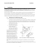
Coastal 14E Ku-Band TVRO 1. Installation Installation Installation of your Coastal Series Antenna system must be accomplished by or under the supervision of an authorized Sea Tel dealer for the Sea Tel Limited Warranty to be valid and in force. Good planning of the installation will provide the best results. Below is some guidance on issues that are important to consider when planning the installation. Planning is the key to a good installation.
Installation Coastal 14E Ku-Band TVRO The ACP and the satellite receiver should be mounted near each other which is connected to each other with a supplied 6 foot RF receiver cable, If enclosed in a cabinet or panel, assure that there is adequate airflow to prevent from over-heating and provide forced airflow if needed. 1.2. Coastal 14E System Inventory Please inventory the contents of the box.
Coastal 14E Ku-Band TVRO 1.6. Installation Prepare the Satellite Receiver and Television mounting locations Prepare the mounting locations for the satellite receiver and television set ( or monitor and stereo sound system). 1.7. Running the Cables 1.7.1. Antenna Cable Route the “F” connector end of the antenna cable down from the radome mounting location through the boat to the antenna control panel location. Adjust the cable routing so that about 12 inches (30.
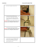
Installation Coastal 14E Ku-Band TVRO 2. Remove the radome top by removing the three screws that thread into the radome base. 3. Set the radome top aside in a safe location until you are ready to close the radome. 4. ***Using caution as to not the Cut the two Tie wraps that attach elevation belt to Pulley, cut the shipping tie-wraps to allow free movement of the antenna mechanism. 5.
Coastal 14E Ku-Band TVRO Installation 6. Tighten all four of the mounting bolts 7. Lift the base of the radome up and connect the antenna cable to the base of the antenna. 8. While being careful not to pinch or kink the antenna cable, set the radome base mounting bolts into the mounting holes. 9. From the underside of the mounting surface, install a ¼” flat washer, a small pattern washer and a nylon lock nut on each of the mounting bolts. 10. Tighten all four of the nuts. 11. Re-install the radome top.
Installation Coastal 14E Ku-Band TVRO 3. Connect the black wire to the - (minus) terminal on the green screw terminal. 4. Connect the antenna cable to the IN connector of the antenna control panel. This IN connection supplies 30VDC operating voltage and antenna control signals to the antenna and receives satellite signal from the antenna. CAUTION: Connecting the satellite receiver to the IN connector may damage the satellite receiver. 5.
Coastal 14E Ku-Band TVRO Installation 1.10. Install the Satellite Receiver and Television Set Connect the receiver cable from the antenna control panel’s RF “Out” Port to the satellite input connection on the rear of your receiver. Connect desired configuration of audio/video cables between the satellite receiver and television set (or monitor & stereo equipment).
Coastal 14E Ku-Band TVRO Setup This Page Intentionally Left Blank 2-0
Coastal 14E Ku-Band TVRO 2. Setup Setup 2.1. System Checkout 1. Press the POWER key on the antenna control panel. The display should report model and software versions, verifying the DC power connection between the antenna control panel and the antenna pedestal assembly. 2. Turn power ON to the satellite receiver and the TV monitor. The television may now be displaying “searching for satellite signal” verifying proper video connections between the receiver and the monitor. 2.2.
Setup Coastal 14E Ku-Band TVRO 2.3.2. Setting Auto Threshold for Proper Tracking Auto Threshold needs to be set to about 1/3rd of the difference in AGC between noise floor (OFF satellite) signal level and peak (ON satellite) signal level. The most common value for the Coastal 14 is 60. 1. Press the NEXT key to SELECT this parameter for adjustment. 2. Once selected, press ▼ & ▲ arrow keys to increment/decrement the indicated digit to the desired value. 3.
Coastal 14E Ku-Band TVRO Setup 7. A cursor will appear under the leftmost character. Press ▼ & ▲ arrow keys to increment/decrement this character. 8. Press the NEXT key to move the cursor to the next character to the right. Press ▼ & ▲ arrow keys to increment/decrement this character. 9. Continue editing characters (6 max) until all desired characters have been set to create the NAME you want to use for this satellite selection. Press the SAVE key to save the NAME parameter for this SAT. 10.
Setup Coastal 14E Ku-Band TVRO can press the ▼ arrow key to go to next SAT numeric menu choice or to the Factory Settings menu choice. 2.3.3.5. Hi Band Vertical Frequency Enter or edit the Ku Hi Band Vertical Frequency (in MHz) for the receiver to use to track this satellite. Range of acceptable frequency input is 950-2150 MHz. 1. Press the NEXT key to SELECT this sub-menu parameter for adjustment. 2. A cursor will appear under the rightmost digit.
Coastal 14E Ku-Band TVRO Setup 15. Press the NEXT key to move the cursor to the digit to the left. Press ▼ & ▲ arrow keys to increment/decrement this digit. 16. Continue editing until all 4 digits have been set to the desired tracking Frequency for this satellite selection. Press the SAVE key to save the FREQ parameter for this SAT. 17. If you want to edit any of the other default values that are loaded with preset, press the ▼ arrow key to go to the next sub-menu parameter. 18.
Setup Coastal 14E Ku-Band TVRO 2.3.3.10. Lo Band FEC Rate Enter or edit the Lo Band Forward Error Correction rate for the receiver to use for this satellite. This choice presets all of the other sub-menu parameters to factory defaults for the satellite you choose to set this SAT to. 31. Press the NEXT key to SELECT this parameter for adjustment. 32. Once selected, press ▼ & ▲ arrow keys to scroll through a list of choices which this SAT can be preset to.
Coastal 14E Ku-Band TVRO Setup 37. Once selected, press ▼ & ▲ arrow keys to scroll through a list of choices which this SAT can be preset to. This list may change in future software revisions. The current choices are: AUTO Automatically scans through all the standard DVB & DSS FEC rates. 1/2 2/3 3/4 5/6 6/7 7/8 AUTO* Automatically scans through all the available forced * (star’ed) FEC rates.
Setup Coastal 14E Ku-Band TVRO 46. If you do not want to edit any other sub-menu parameters, press SAVE again to exit the sub-menu and return to the SAT main menu display. From there you can press the ▼ arrow key to go to next SAT numeric menu choice or to the Factory Settings menu choice. 2.3.3.13. Hi Band NID Enter or edit the Hi Band Network ID 4 digit HEX value for the receiver used to Identify & track this satellite. 47. Press the NEXT key to SELECT this sub-menu parameter for adjustment. 48.
Coastal 14E Ku-Band TVRO 2.3.6.1. Setup Serial Number This parameter sets Serial Number of the Antenna Pedestal into the PCU memory. The serial number starts with 98 followed by 6 digits that are editable. This parameter allows the Serial Number of the Antenna to be displayed on the Display Antenna Control Panel during the initialization process. NOTE: The Serial Number parameter setting is saved in the PCU, therefore, MUST be set whenever the PCU is changed.
Setup Coastal 14E Ku-Band TVRO 1. Press the NEXT key to SELECT this sub-menu parameter for adjustment. 2. A cursor will appear under the leftmost digit. Press ▼ & ▲ arrow keys to increment/decrement this digit. 3. Press the NEXT key to move the cursor to the next digit to the right. Press ▼ & ▲ arrow keys to increment/decrement this digit. 4. Press the NEXT key to move the cursor to the next digit to the right. Press ▼ & ▲ arrow keys to increment/decrement this digit. 5.
Coastal 14E Ku-Band TVRO 3. Maintenance Maintenance 3.1. Warranty Information Sea Tel Inc. supports its Coastal Series systems with a warranty program unsurpassed in the industry. These systems are backed by a TWO YEAR full warranty on parts and a ONE YEAR warranty on labor.
Maintenance 3.3. Coastal 14E Ku-Band TVRO Preventive Maintenance As needed - Clean the outside surface of the radome with warm soapy water to remove dust, grime and salt residue. There is no other preventive maintenance required 3.4. Fault Isolation/Trouble-shooting The following table is provided to help isolate problems in the Coastal Series Antenna system. Symptom Antenna tracking but receiver not providing desired programming Possible Fault 1. Incorrect satellite.
Coastal 14E Ku-Band TVRO 3.5. Maintenance Antenna tracks well at the pier, but loses the satellite when underway 1. Call dealer/agent for further assistance Antenna does not stay on satellite at pier, or underway 1. Check all coax cables for poor connection 2. Call dealer/agent for further assistance Linear Polarization Adjustment As the polarization is mis-adjusted, the signal level will degrade. If it is mis-adjusted far enough, the signal will be completely lost.
Maintenance Coastal 14E Ku-Band TVRO 3.5.2. Setting polarization for a different satellite (changing satellites) When changing from one satellite to another you may need to adjust the polarization of the LNB to be able to acquire the satellite you want to switch to. This will only be required if the difference in polarization angle of the two satellites is greater than ten degrees. 1. Assure that you have optimized the polarization for the satellite you are presently on. 2.
Coastal 14E Ku-Band TVRO 4. Coastal 14E Technical Specifications Coastal 14E Technical Specifications 4.1. Installed Weight Total Weight (dry): 4.2. 25 lbs. (11.3 kg) Radome Diameter 16.5 inch (41.9cm) Height 18 inch (45.7cm) Mounting (Base to Deck) (Qty 4) ¼-20 fasteners Mounting (Top to Base) (Qty 3) 8/32 x 5/8” Flat Head screws Wind: Withstand relative average winds up to 100 MPH from any direction. Ingress Protection Rating All Sea Tel radomes have an IP rating of 56 4.3.
Coastal 14E Technical Specifications Coastal 14E Ku-Band TVRO Maximum Ship Motion Roll +/- 25 degrees Pitch +/- 15 degrees Elevation Pointing 4.5. +/- 15 degrees of Roll 35 to 60 degrees +/- 25 degrees of Roll 40 to 50 degrees Universal Single Flange Linear Sea Tel Part Number: 127113 Type: Single “f” connector output LNB Manufacturer: Inverto, IDLP-SFLANGE, but may vary Low Band High Band (22Khz Tone On) (22Khz Tone OFF) RF Frequencies: 10.7 -11.7Ghz 11.7 – 12.
Coastal 14E Ku-Band TVRO Coastal 14E Technical Specifications Output RF Level Input level +/- 1 dB typical Sensitivity 30 mV / dB typical Bandwidth Selectable 7.5-30 MHz in DVB Mode, Polarity switching 13 VDC output to select Vertical polarity. 18 VDC to output select Horizontal polarity 4.7. Band Switching: 22kHz continuous tone output to select High band, No tone to select Low band. Satellite ID Network ID for DVB signals.
Coastal 14E Technical Specifications 4.9. Coastal 14E Ku-Band TVRO Antenna Control Panel Size: 2.08 x 4.93 x 2.43 inches (5.28 x 12.52 x 6.17 cm) Features: Liquid Crystal Display (16 Character x 2 Line) with Adjustable Backlight , 2 indicator LED’s (Unwrap and Tracking),BDE FSK Multiplexer, 4 Amp inline fuse, IF Output Port with builtin Voltage and 22Khz Continuous Tone Detector Circuits.
Coastal 14E Ku-Band TVRO 5. Computer Interface Computer Interface A computer may be connected to the antenna control panel to allow you to provide access to ALL the parameter settings of the Coastal Series antenna and to perform Software Uploads to the Pedestal Control Unit. The commands to set the parameters in the Coastal Series PCU are summarized below. Changing the parameters for the desired satellites may be easily done using the computer interface.
Computer Interface Coastal 14E Ku-Band TVRO 7 Check “Send line ends with line feeds”, “Echo typed characters locally” and “Append line feeds to incoming line ends”. Click OK. 8 Type ^0086 and hit ENTER. 9 Refer to the command information below to communicate with the antenna system. The Display Antenna Control Panel will be locked while you are connected to the computer. 10 When you are finished, close the terminal program and disconnect the computer from the Display Antenna Control Panel.
Coastal 14E Ku-Band TVRO 6. Drawings Drawings The following drawings are included with this manual for installation and maintenance reference. 6.1.
Drawings Coastal 14E Ku-Band TVRO This page left blank intentionally 6-2
SINGLE LEVEL MFG BILL OF MATERIAL FIND QTY PART NO REV DESCRIPTION REFERENCE DESIGNATOR 1 1 EA 127109-1 A GENERAL ASS'Y, COASTAL 14E 2 1 EA 125822 D RADOME ASS'Y, COASTAL 14 3 1 EA 126059 A ANTENNA CONTROL PANEL ASS'Y, TACP 4 1 EA 113480-1 C1 CABLE ASS'Y, RF, RG6, 50 FT. 5 1 EA 111115-6 B CABLE ASS'Y, F(M)-F(M), 6 FT.
Drawings Coastal 14E Ku-Band TVRO Page 2 of 2 6-4
Coastal 14E Ku-Band TVRO 127110 Drawings System Block Diagram 6-5
Drawings Coastal 14E Ku-Band TVRO Page 2 of 2 6-6
Coastal 14E Ku-Band TVRO 127111 Drawings Antenna Schematic 6-7
Drawings 127109 Coastal 14E Ku-Band TVRO General Assembly 6-8
Coastal 14E Ku-Band TVRO Drawings Page 2 of 3 6-9
Drawings Coastal 14E Ku-Band TVRO Page 3 of 3 6-10
Coastal 14E Ku-Band TVRO 127112 Drawings Antenna Assembly 6-11
Drawings Coastal 14E Ku-Band TVRO Page 2 of 2 6-12
Coastal 14E Ku-Band TVRO 125822_C Drawings Radome Assembly 6-13
Drawings Coastal 14E Ku-Band TVRO Page 2 of 2 6-14
Coastal 14E Ku-Band TVRO 126357_A1 Drawings Installation Arrangement 6-15
Drawings 127247 Coastal 14E Ku-Band TVRO Packing List Coastal 14 6-16
Coastal 14E Ku-Band TVRO Page 2 of 2 Drawings Packing List Coastal 14 6-17