
System information


Basic System Information DAC-2202 Antenna Control Unit
3-4
Fi
g
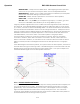
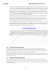
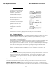
ure 3-2 Circular and Linear Polarization
3.2.4. Antenna polarization
If you have a circular polarization
LNB installed, you do not need
to adjust the “polarization” of
the antenna. If you have a linear
polarization LNB installed, the
system should have been
adjusted properly and set-up in
Auto-Polarization mode. Auto-
Polarization makes small
polarization adjustments
periodically as the boat changes
geographic locations by a
significant amount of latitude
and longitude. It also adjusts the
polarization of the feed when
changing from one satellite to
another.
Once polarization adjustment has been optimized, it is NOT necessary to readjust it as long as
the boat remains in the same geographic area and stays on the same satellite.
3.2.5. Tracking Receivers
Satellite Identification Receiver - The Satellite Identification Receiver located in the Antenna
Control Unit (ACU) is used to acquire, identify and track a specific satellite by its unique
hexadecimal ID code. When properly setup, the settings for the satellite are saved to expedite
future acquisition of the desired satellite.
When searching for the selected satellite this receiver compares the programmed satellite ID to
the received satellite ID code. If the ID code does not match the antenna will continue
searching until the correct satellite ID is found. The system must have adequate satellite signal
level (on the frequency you are tuned to and at the baud rate & FEC rate you have the receiver
set to), AND the matching NID, to stop searching (and begin tracking the desired satellite).
If you have the optional Touch Screen Controller (TSC-10) you can setup multiple “favorite
satellites” and subsequently switch to different “favorite” satellite in two touches on the
screen.
3.2.6. Tracking
The ACU actively optimizes the pointing of the dish for maximum signal reception. This process
is called tracking and is accomplished by continuously making small movements of the dish
while monitoring the level of the received signal. Evaluation of this information is used to
continuously make minor pointing corrections to keep the signal level “peaked” as part of
normal operation.
3.3. Components of the System Configuration
The following text provides a basic functional overview of the system components and component
interconnection as referred to in the System Block Diagram for your model antenna.
Television Receive Only (TVRO) Systems are comprised of two major sections: The Above-Decks
Equipment (ADE) is comprised of the Sea Tel antenna & radome assembly which is mounted outside, on