
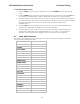
System information
Functional Testing DAC-2202 Antenna Control Unit
6-2
6.5. Four Quadrant Tracking Test
This verifies that the antenna moves in the correct response to the keys, that Tracking is signaling
correctly and that the Tracking commands are being carried out (antenna drives to peak).
1. Verify antenna is locked onto and tracking a satellite
2. Press the NEXT key several times to display the Antenna menu.
3. Note the current peak AGC value. Press the Tracking key to toggle Tracking OFF, press the UP
arrow key repeatedly to move the antenna up in elevation until AGC falls about 100 counts. Turn
Tracking ON and verify that the antenna moves back down in elevation and that the AGC rises to
its’ previous high value.
4. Note the current peak AGC value. Press the Tracking key to toggle Tracking OFF, press the
DOWN arrow key repeatedly to move the antenna down in elevation until AGC falls about 100
counts. Turn Tracking ON and verify that the antenna moves back up in elevation and that the
AGC rises to its’ previous high value.
5. Note the current peak AGC value. Press the Tracking key to toggle Tracking OFF, press the
RIGHT arrow key repeatedly to move the antenna up in azimuth until AGC falls about 100
counts. Turn Tracking ON and verify that the antenna moves back down in azimuth and that the
AGC rises to its’ previous high value.
6. Note the current peak AGC value. Press the Tracking key to toggle Tracking OFF, press the
LEFT arrow key repeatedly to move the antenna down in azimuth until AGC falls about 100
counts. Turn Tracking ON and verify that the antenna moves back up in azimuth and that the
AGC rises to its’ previous high value.
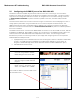
6.6. Blockage Simulation Test
Blockage output function is used to modify the behavior of Tracking and Searching when there is a
known blockage zone. The ACU provides a contact closure to ground on the SW2 terminal of the
Terminal Mounting Strip when the antenna is pointed within any one of the blockage/hazard zones or the
system is searching, targeting, unwrapping or is mis-pointed by 0.5 degrees or more (FCC TX Mute
function for Transmit/Receive systems only). The contact closure is a transistor switch with a current
sinking capability of 0.5 Amp. This logic output control signal is used for:
• When used as simple “BLOCKED” logic output for a single Sea Tel antenna, this output could be
used to light a remote LED and/or sound a buzzer to alert someone that the antenna is blocked,
and signal is lost.
• In a “Dual Antenna” installation, this logic output(s) is used to control Dual Antenna Arbitrator
panel of coax switches to switch the source inputs to the matrix switch from Antenna “A” to
Antenna “B”, and vice versa.
• When used as simple “RF Radiation Hazard” logic output for a single Sea Tel TX/RX antenna,
this output could be used to suppress RF transmissions while the antenna is pointed where
people would be harmed by the transmitted microwave RF power output. The SW2 output
would be interfaced to the satellite modem to disable the TX output signal from the Satellite
TXRX Modem whenever the antenna is within the RF Radiation Hazard zone(s).
• When used for “FCC TX Mute” logic output for a single Sea Tel TX/RX antenna, this output
could be used to suppress RF transmissions whenever the antenna is mis-pointed 0.5 degrees
or more, is blocked, searching, targeting or unwrapping. The SW2 output would be interfaced to
the satellite modem to disable/mute the TX output signal from the Satellite TX/RX Modem.
When the mute condition is due to antenna mis-pointing, it will not un-mute until the pointing
error of the antenna is within 0.2 degrees. The default output is contact closure to ground when
the antenna is mis-pointed, therefore provides a ground to “Mute” the satellite modem on the
SW2 terminal of the Terminal Mounting Strip. If your satellite modem requires an open to
“Mute”, refer to SYSTEM TYPE parameter 16 value to reverse the output logic from the ACU.