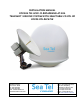
INSTALLATION MANUAL FOR SEA TEL 6009-33 BROADBAND-AT-SEA TRANSMIT / RECEIVE SYSTEM WITH SELECTABLE CO-POL OR CROSS-POL RECEIVE Sea Tel, Inc. 4030 Nelson Avenue Concord, CA 94520 Tel: (925) 798-7979 Fax: (925) 798-7986 Email: seatel@cobham.com Web: www.cobham.com\seatel December 7, 2009 Sea Tel Europe Unit 1, Orion Industrial Centre Wide Lane, Swaythling Southampton, UK S0 18 2HJ Tel: 44 (0)23 80 671155 Fax: 44 (0)23 80 671166 Email: seatel@cobham.com Web: www.cobham.
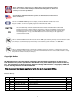
These commodities, technology or software were exported from the United States in accordance with the Export Administration Regulations. Diversion contrary to U.S. law is prohibited. Sea Tel Marine Stabilized Antenna systems are manufactured in the United States of America. Sea Tel is an ISO 9001:2000 registered company. Certificate Number 19.2867 was issued August 12, 2005. Sea Tel was originally registered on November 09, 1998.
Table of Contents 1. 2. 3. 6009-33 Installation Manual 09 SERIES SYSTEM CONFIGURATION(S)................................................................................................................................... 1-1 1.1. SERIES 09 BASIC SYSTEM INFORMATION ................................................................................................................................................ 1-1 1.2. SYSTEM CABLES ............................................................................
009-33 Installation Manual Table of Contents CONNECTING THE BELOW DECKS EQUIPMENT ........................................................................................................................................ 3-6 3.6.1. Connecting the ADE AC Power Cable ............................................................................................................................ 3-6 3.6.2. Connecting the BDE AC Power Cables ..........................................................................
Table of Contents 10. 11. 12. 13. 14. 6009-33 Installation Manual 9.2.4. STEP INTEGRAL ..........................................................................................................................................................................9-4 9.2.5. SEARCH INC .................................................................................................................................................................................9-4 9.2.6. SEARCH LIMIT .........................
6009-33 Installation Manual Table of Contents 14.5. FOUR QUADRANT TEST TRACKING.......................................................................................................................................................... 14-2 14.6. BLOCKAGE SIMULATION TEST .................................................................................................................................................................. 14-3 14.7. TEST BROADBAND OPERATION .........................................
Table of Contents 6009-33 Installation Manual 17.9.1. Climatic Conditions ...............................................................................................................................................................17-5 17.9.2. Chemically Active Substances .........................................................................................................................................17-5 17.9.3. Mechanical Conditions ...............................................................
6009-33 Installation Manual Table of Contents This Page Intentionally Left Blank x
09 Series System Configuration(s) 1. 6009-33 Installation Manual 09 Series System Configuration(s) The 09 Series Stabilized Antenna system is to be used for Transmit/Receive (TX/RX) satellite communications, it is comprised of two major groups of equipment. These are the Above Decks Equipment (ADE) and the Below Decks Equipment (BDE). There will also be interconnecting cables between the ADE & BDE and cables to provide other inputs to the system. 1.1.
6009-33 Installation Manual 09 Series System Configuration(s) 1.5.Dual Antenna Configuration Sometime, due to very large blockage conditions, you may need to install a dual antenna configuration to provide uninterrupted services. Two full antenna systems are installed and the ACU control outputs are connected to an arbitrator switch panel which then is connected to the below decks equipment.
09 Series System Configuration(s) 1.6. 6009-33 Installation Manual Dual Antenna Arbitrator The Dual Antenna Arbitrator panel can pass LNB voltages (and handle 250-400 ma of current) and the RXIF signals on the RX connections. TXIF, Reference and BUC supply voltage can be passed through this arbitrator panel to the antenna, but it is not recommended that BUC power be supplied through the dual channel rotary joint of the antenna (a BUC power supply is provided on all Series 09 Antenna Pedestals).
6009-33 Installation Manual 09 Series System Configuration(s) the parameters of both the satellite modem (proper option files) and the ACU/PCU (setup parameters) are actually compatible for the intended satellite(s). 1.7.2. Interface requirements: 1.7.2.1. Hardware Sea Tel Antenna Control Units Model DAC2202 or DAC2302. Any Satellite modem manufacturer that is compatible with OpenAMIP CAT5 Patch cable 1.7.2.2. Software Sea Tel model DAC2202: ACU software version 6.
Site Survey 2. 6009-33 Installation Manual Site Survey The objective of the Site survey is to find the best place to mount the antenna & the below decks equipment, the length and routing of the cables and any other items or materials that are required to install the system and identify any other issues that must be resolved before or during the installation.
6009-33 Installation Manual Site Survey the deck/deckhouse structure is prescribed by the ship’s classification society. In the deck/deckhouse design rules, the minimum plating and stiffener guidelines are chosen to preclude high local vibration amplitudes. Most installations onto a deck or deckhouse structure will require a mounting pedestal to raise the ADE above the deck for radome hatch access and to allow the full range of elevation (see ADE mounting considerations above).
Site Survey 6009-33 Installation Manual When the g-force exerted on the antenna is light, antenna stabilization and overall performance will not be affected. If the g-force exerted on the antenna is high enough (> 1 G), antenna stabilization and overall performance will be affected. If the g-force exerted on the antenna is excessive (1-2 Gs), the antenna will not maintain stabilization and may even be physically damaged by the g-force. 2.5.
6009-33 Installation Manual Site Survey If the estimated natural frequency of the mast or platform is less than 35 Hertz, the mast or platform should be stiffened by the addition of deeper gussets under the platform or behind the mast. 2.5.2. Raked Masts Raked masts are found on vessels where the style or appearance of the entire vessel is important.
Site Survey 6009-33 Installation Manual 2.5.4. Truss Mast Truss masts are a variant on the girder mast concept. Rather than a pair of columns supporting a girder beam, the construction is a framework of tubular members supporting a platform on which the antennae and other equipment is mounted. A typical truss mast is shown in this photograph. Like a girder mast, truss masts are especially stiff in the athwart ship direction.
6009-33 Installation Manual 2.8.1. Site Survey ADE/BDE Coaxial Cables The first concern about the coaxial cables installed between the ADE & BDE is length. This length is used to determine the loss of the various possible coax, Heliax or fiber-optic cables that might be used. You should always provide the lowest loss cables to provide the strongest signal level into the satellite modem.
Installation 3. 6009-33 Installation Manual Installation Your antenna pedestal comes completely assembled in its radome. This section contains instructions for unpacking, final assembly and installation of the equipment. It is highly recommended that installation of the system be performed by trained technicians. Your antenna may have been ordered in a 76” diameter radome or an 81” diameter radome. The installation instructions for both radome sizes are below. 3.1.
6009-33 Installation Manual Installation CAUTION: The antenna/radome assembly is very light for its size and is subject to large swaying motions if hoisted under windy conditions. Always ensure that tag lines, attached to the radome base frame, are attended while the antenna assembly is being hoisted to its assigned location aboard ship. WARNING: Assure that all nut & bolt assemblies are tightened according the tightening torque values listed below: SAE Bolt Size Size 3.3.1.
Installation 6009-33 Installation Manual 3.3.2. Install 76” Radome to mounting deck. The antenna pedestal is shipped completely assembled, restrained for shipping, in its radome. WARNING: Hoisting with other than a webbed four-part sling may result in catastrophic crushing of the radome. Refer to the specifications and drawings for the fully assembled weight of your model Antenna/Radome and assure that equipment used to lift/hoist this system is rated accordingly.
6009-33 Installation Manual 2. 3. 4. 5. 6. 7. 8. Installation Attach a four-part lifting sling to the four lifting eyes in the base of the radome and lift the radome assembly free of its shipping pallet. Place the radome assembly on temporary support blocks at least 22 inches high. Loosely assemble the radome base frame's eight legs and eleven braces as shown in the Radome Base Frame Assembly drawing using the hardware provided. Insure that a split washer is used under each nut.
Installation 6009-33 Installation Manual 3.5.1. General Cautions & Warnings CAUTION - Electrical Shock Potentials exist on the Gyro Compass output lines. Assure that the Gyro Compass output is turned OFF when handling and connecting wiring to the Terminal Mounting Strip. CAUTION - Allow only an authorized dealer to install or service the your Sea Tel System components. Unauthorized installation or service can be dangerous and may invalidate the warranty. 3.5.2.
6009-33 Installation Manual 4. Installation Install your Satellite Modem, Router, VOIP adapters, Telephone equipment, Fax machine, Computers and any other below decks equipment that are part of your installation. 3.6.Connecting the Below Decks Equipment Connect this equipment as shown in the System Block Diagram. 3.6.1. Connecting the ADE AC Power Cable Connect the AC Power cable that supplies power to the ADE to a suitably rated breaker or UPS. 3.6.2.
Installation 6009-33 Installation Manual extension cable. Another choice is to connect the “ETHERNET” connector on the rear panel of the ACU to a LAN connection on the computer or hub using an Ethernet crossover cable. 3.6.6. Radio Control Serial Cable If desired, connected the Radio Control Serial Cable from the Base Multiplexer to the COM Port of a Customer Furnished Computer. 3.6.7.
6009-33 Installation Manual Installation frequency to 0000. Normally, AGC readings below 2048 are considered a low condition and indicate modem lock and AGC readings above 2048 are considered a high condition and indicate modem unlock. [If you find the AGC reading for locked and unlocked conditions need to be reversed you must add 128 to your current SYSTEM TYPE parameter]. Turn tracking OFF when checking the external AGC inputs.
Installation 6009-33 Installation Manual • 3.6.7.7. 3.6.8. 12/24 Screw terminal is commonly used to provide operating voltage to a external GPS, Dual Antenna Arbitrator or other below decks tone generators or switches. Voltage output is based on the T.M.S assemblies JP5 jumper settings. TS5 NMEA A/B, GPS output. • RxA- and RxA+- screw terminals, which are defined as the NMEA A connection is used to connect to the ships Gyro Compass (Heading).
6009-33 Installation Manual Installation drive must be OFF to balance the antenna. . Do NOT remove any of the drive belts. Balancing is accomplished by adding or removing balance trim weights at strategic locations to keep the antenna from falling forward/backward or side to side. The antenna system is not pendulous so 'balanced' is defined as the antenna remaining at rest when left in any position. The “REMOTE BALANCE” parameter (located at the end of the Remote Parameters after REMOTE TILT) of the ACU.
Installation 6009-33 Installation Manual • A normal trace display will be ± 1 divisions from the red reference line while under calm sea conditions and with DishScan Drive turned off. See example below • The Cross Level display will decrease (plots below red line) as the antenna requires drive to the left and increase (plots above red line) as the antenna requires to the right. Example: The antenna pictured in the screen capture below is imbalanced so that it is “Right Heavy”.
6009-33 Installation Manual • Installation The Azimuth display should decrease (plots below red line) as the antenna is driven CCW and increase (plots above red line) as the antenna is rotated CW.
Basic Setup of the ACU 4. 6009-33 Installation Manual Basic Setup of the ACU 4.1.Operator Settings Refer to the Operation chapter of this manual to set the Ship information. Latitude and Longitude should automatically update when the GPS engine mounted on the antenna pedestal triangulates an accurate location, but you may enter this information manually to begin.
6009-33 Installation Manual Basic Setup of the ACU AZ LIMIT 1 0 AZ LIMIT 2 0 EL LIMIT 12 90 AZ LIMIT 3 0 AZ LIMIT 4 0 EL LIMIT 34 90 AZ LIMIT 5 0 AZ LIMIT 6 0 EL LIMIT 56 90 5v OFFSET 0 5V SCALE Setup – Blockage & RF Radiation Hazard Zones Leave at factory Defaults 0 Leave at factory Defaults TX POLARITY 2 (Horizontal TX) Setup – Optimizing Polarity & Cross Pol Isolation TRACK DISP 130 or 170 Setup – Band Selection * This setting is for the i-Direct 5000 Series modem to prov
Setup – Ships Gyro Compass 5. 6009-33 Installation Manual Setup – Ships Gyro Compass The Ships Gyro Compass connection provides true heading (heading of the ship relative to true North) input to the system. This allows the ACU to target the antenna to a “true” Azimuth position to acquire any desired satellite. After targeting this input keeps the antenna stabilized in Azimuth (keeps it pointed at the targeted satellite Azimuth).
6009-33 Installation Manual Setup – Ships Gyro Compass This Page Intentionally Left Blank 5-2
Setup – Band Selection 6. 6009-33 Installation Manual Setup – Band Selection To properly control the band selection of the LNB(s) mounted on the antenna the TRACK DISP (Tracking Display) parameter must be set correctly. Which value the TRACK DISP parameter is set to depends on the hardware configuration of the antenna pedestal.
6009-33 Installation Manual Setup – Band Selection This Page Intentionally Left Blank 6-2
Setup – Targeting 7. 6009-33 Installation Manual Setup – Targeting In this lesson you will learn how to optimize the targeting of the antenna to land on or near a desired satellite (within +/-1 degree). 7.1.AUTO TRIM The Auto Trim function will automatically calculate and set the required Azimuth and Elevation trim offset parameters required to properly calibrate the antennas display to the mechanical angle of the antenna itself.
6009-33 Installation Manual Setup – Targeting Continue with Azimuth trim, then re-target the satellite several times to verify that targeting is now driving the antenna to a position that is within +/- 1.0 degrees of where the satellite signal is located. 7.4.AZ TRIM Azimuth trim offset parameter is entered in tenths of degrees. Offsets true azimuth angle display to compensate for installation alignment errors when used with Ships Gyro Compass input reference.
Setup – Home Flag Offset 8. 6009-33 Installation Manual Setup – Home Flag Offset Home Flag Offset is used to calibrate the relative azimuth value of the antenna to the bow line of the ship. This assures that the encoder input increments/decrements from this initialization value so that the encoder does not have to be precision aligned. When the antenna is pointed in-line with the bow (parallel to the bow) the “Relative” display value should be 000.0 Relative (360.0 = 000.0).
6009-33 Installation Manual Setup – Home Flag Offset If AZ TRIM was a plus value: HFO = (TRIM / 360) x 255 Example: AZ TRIM was 0200 (plus 20 degrees). HFO = (20/360) x 255 = (0.0556) x 255 = 14.16 round off to 14. Set, and Save, HFO to 014 using the “To Enter the HFO value” procedure below. If AZ TRIM was a negative value: HFO = ((360-TRIM) / 360)) x 255 Example: AZ TRIM = -0450 (minus 45 degrees). HFO = ((360 – 45) / 360)) x 255 = (315 / 360) x 255 = 0.875 x 255 = 223.125 round of to 223.
Setup – Home Flag Offset 6009-33 Installation Manual “home” was to the right of bow) this difference of 09.0 to the bow line position 000.0. Therefore “home” should be 90.0 Relative. 8. I now calculate the HFO = = ((90.0) / 360)) x 255 = 0.25 x 255 = 63.75 which I round off to 64. 9. I set, and Save, HFO to 222 using the “To Enter the HFO value” procedure below. After I re-initialize the relative position of the antenna is now calibrated. 10.
6009-33 Installation Manual Setup – Home Flag Offset 8.2.Mechanical Calibration of Relative Antenna Position (Home Flag Offset) During initialization, azimuth drives the antenna CW until the Home Flag Switch senses the trailing edge of the metal tab (as shown in the left picture above). The sensor will appear to go past the metal tab, then come back to the trailing edge of the metal tab and stay there.
Setup – Searching 9. 6009-33 Installation Manual Setup – Searching 9.1.Searching Operation The ACU will initiate an automated search pattern after AGC falls below the current Threshold setting (indicates that satellite signal has been lost). The SEARCH DELAY parameter sets the amount of delay, in seconds, that the ACU will wait after AGC has fallen below the threshold value before it starts a search.
6009-33 Installation Manual 9.1.2. Setup – Searching Inclined Orbit Search Pattern Some older satellites, in order to save fuel to keep them exactly positioned over the Equator, are in an inclined geosynchronous orbit. The satellite remains geosynchronous but is no longer geostationary. From a fixed observation point on Earth, it would appear to trace out a figure-eight with lobes oriented northsouthward once every twenty-four hours.
Setup – Searching 6009-33 Installation Manual You configure the ACU to use this pattern by using the following settings: SEARCH INC - set to the default value for the frequency band that your antenna model is currently being used for (typically 10 counts). SEARCH LIMIT – leave this set to the default value. SEARCH DELAY – default, or any number of seconds from 1-255 that you would prefer that the ACU wait before starting an automatic search.
6009-33 Installation Manual 9.2.1. Setup – Searching AUTO THRES Sets offset of AGC tracking threshold above the average noise floor. Units are in A/D counts, approximately 20 counts/dB. A setting of 0 disables auto threshold, therefore, the operator would have to manually enter a threshold value. When AUTO THRESHOLD is enabled (any value between 1-255), the ACU automatically re-sets the AGC tracking threshold whenever the antenna Targets (AZ, EL or SAT) or Searches.
Setup – Searching 6009-33 Installation Manual Use the LEFT or RIGHT arrow key to move the cursor left or right to select other characters to modify. When you are finished modifying press ENTER to execute the new value OR press NEXT to abort and exit setup mode. 9.2.6. SEARCH LIMIT Sets the overall peak to peak size of the search pattern. Units are in pedestal step resolution (12 steps per degree). Default value is 100 for all 09 systems.
6009-33 Installation Manual Setup – Searching This Page Intentionally Left Blank 9-6
Setup – Blockage & RF Radiation Hazard Zones 10. 6009-33 Installation Manual Setup – Blockage & RF Radiation Hazard Zones This section discusses how to set up blockage, or RF Radiation Hazard, zones in the ACU. 10.1. Radiation Hazard and Blockage Mapping (AZ LIMIT parameters) The ACU can be programmed with relative azimuth sectors (zones) where blockage exists or where transmit power would endanger personnel who are frequently in that area.
6009-33 Installation Manual Setup – Blockage & RF Radiation Hazard Zones When used for “FCC TX Mute” logic output for a single Sea Tel TXRX antenna, this output is used to suppress RF transmissions whenever the antenna is mis-pointed 0.5 degrees or more, is blocked, searching, targeting or unwrapping. The SW2 output would be interfaced to the satellite modem to disable/mute the TX output signal from the Satellite TXRX Modem.
Setup – Blockage & RF Radiation Hazard Zones 6009-33 Installation Manual EXAMPLE 2 - Three blockage Zones, Dual Antenna configuration: A ship has 2 Sea Tel antennas, “Antenna A” mounted on the port side and “Antenna B” mounted on the starboard side. Antenna A is designated as the master antenna and its zones would be set as in example 1 above. The mast forward, Antenna A to port and the engine exhaust stack aft form the three zones where satellite signal is blocked from Antenna B.
6009-33 Installation Manual Setup – Blockage & RF Radiation Hazard Zones ZONE 2 is not needed. Enter AZ LIMIT 3 value of 0000 and AZ LIMIT 4 value of 0000. Set EL LIMIT 34 to 0000. ZONE 3 is not needed. Enter AZ LIMIT 5 value of 0000 and AZ LIMIT 6 value of 0000. Set EL LIMIT 56 to 0000. ZONE 4 is not needed. Enter AZ LIMIT 7 value of 0000 and AZ LIMIT 8 value of 0000. Set EL LIMIT 78 to 0000. If your ACU software includes 5 volt polarization you will not see these AZ & EL LIMIT parameters.
Setup – Modem Connections, Setup and Test 11. 6009-33 Installation Manual Setup – Modem Connections, Setup and Test In order to be compliant with FCC Order 04-286 and WRC-03 Resolution 902 the Satellite Modem MUST be connected to the Antenna control Unit/Terminal Mounting Strip to provide TX Mute control functionality. The FCC/WARC requirements have been adopted by ITU & ETSI for them to publish similar requirements.
6009-33 Installation Manual 11.4. Setup – Modem Connections, Setup and Test Connections (ACU to Satellite Modem) 11.4.1. iDirect Modems Infinity 3100 - Use an RJ-45 straight serial cable connected from the Terminal Mounting Strip “Console Port” connector to the Console Port connector on the rear panel of the modem. Infinity 5100 - Use an RJ-45 straight serial cable connected from the Terminal Mounting Strip “Console Port” connector to the Console Port connector on the rear panel of the modem. 11.4.2.
Setup – Modem Connections, Setup and Test 6009-33 Installation Manual The functions below can be enabled to change the normal behavior of the system if desired. Select system options according to the following table. Add together all the desired options and enter the sum into the SYSTEM TYPE parameter to enable the desired functions. 128 64 32 16 8 4 2 1 Reverse External Modem Lock input polarity (logic hi = lock).
6009-33 Installation Manual • Setup – Modem Connections, Setup and Test When used as simple “RF Radiation Hazard” logic output for a single Sea Tel TX/RX antenna, this output could be used to suppress RF transmissions while the antenna is pointed where people would be harmed by the transmitted microwave RF power output. The SW2 output would be interfaced to the satellite modem to disable the TX output signal from the Satellite TXRX Modem whenever the antenna is within the RF Radiation Hazard zone(s).
Setup – Modem Connections, Setup and Test 6009-33 Installation Manual to change the next digit. Continue until frequency value, recorded in step 3, is displayed and press the ENTER key to re-tune the tracking receiver. 11.8. SAVE NEW PARAMETERS Parameters that have been changed are only temporarily changed until they are SAVED. If changes are made and not stored, they will still be effective but will be lost when power is removed or the RESET key is pressed.
09-33 Installation Manual Setup – Modem Connections, Setup and Test This Page Intentionally Left Blank 11-6
Setup – Optimizing Polarity & Cross-Pol Isolation 12. 6009-33 Installation Manual Setup – Optimizing Polarity & Cross-Pol Isolation The only way to optimize the polarization of the antenna properly is to peak the polarity angle while the system is in autopolarization mode. This automatically adjusts the polarization of the feed by calculating the required polarization angle for the feed every 2 seconds based on ship's Latitude, Longitude and the desired Satellite Longitude. 12.1.
6009-33 Installation Manual Setup – Optimizing Polarity & Cross-Pol Isolation 8. Make a series of small changes in the opposite direction until you see the signal peak and then fall the same amount as noted in step 6. 9. Note this SAT SKEW value. 10. Set SAT SKEW to mid way between the value noted in step 7 & 9. 11. Save your new SAT SKEW value. 12.4.
Setup – Other Parameters 13. 6009-33 Installation Manual Setup – Other Parameters 13.1. SETUP Parameter display and entry menus. Press and hold BOTH the LEFT and the RIGHT arrow keys for 6 seconds to access to the system setup parameters (at the EL TRIM selection). Press BOTH the LEFT and the RIGHT arrow keys momentarily to access to the SAVE NEW PARAMETERS parameter. Access is only required after installation or repairs of your antenna system.
6009-33 Installation Manual 13.7. Setup – Other Parameters Satellite Reference Mode The ships gyro compass input to the ACU may be accurate and stable in static conditions and yet may NOT be accurate or stable enough in some underway dynamic conditions. If there is no gyro compass or if the input is corrupt, not stable or not consistently accurate the tracking errors will become large enough to cause the antenna to be mispointed off satellite.
Setup – Other Parameters 6009-33 Installation Manual 2. Connect J3 M&C Port to Computer Com Port using a Male to Female RS232 Straight 9 wire serial cable 3. Turn Power on to ACU and then open Sea Tel’s ProgTerm M&C software program. 4. Configure ProgTerm’s Translation Mode. Click on “CommPort” then select “Dac 2200 to ACU (9600)”. Insure that the bottom of screen reads “DAC 2K Translation ACU” 5. Mouse Click on the Paper Clip icon and verify response to ACU status query similar to what’s shown.
6009-33 Installation Manual 7. Setup – Other Parameters To View Communication settings type in DAC2202 Comm IF Commands: “[?↵”. That’s left bracket, question mark, ” [Innn.nnn.nnn.nnn↵ Set IP address [Nnnn.nnn.nnn.nnn↵ Set Net mask. [Gnnn.nnn.nnn.nnn↵ Set Gateway address (Typed characters will not display unless “Echo” is turned on in the Comm Port Properties.
Setup – Other Parameters 9. 6009-33 Installation Manual To save parameters to Flash (Comm IF PCB) Type “[W↵”. That’s Left Bracket, Capital “W”, (No Spaces). Verify “Done” is displayed after Saving Comm parameters. **Do not turn power off to ACU until finished** 10. To reboot Comm IF software Type “[Z↵”. That’s Left Bracket, Capital “Z”, (No Spaces). Verify “Comm IF Ver x.xx Port M&C (C)” is displayed. 13.10.
6009-33 Installation Manual 13.10.1. Number 1 2 3 4 5 6 7 8 Setup – Other Parameters System Information Description Click to redirect to the Port Settings Page. This page presents the TCP connection and baud rate settings for the Comm If Module. Click to redirect to the DAC Parameters 1 Page. This page presents the current ACU configuration parameter values stored in the 68HC08 processor. Click to redirect to the DAC Parameters 2 Page.
Setup – Other Parameters 13.10.2. Number 1 2 3 4 5 6 6009-33 Installation Manual Communication Port Settings Description The IP Address field presents the Static Internet Protocol address value currently stored in the Comm IF module (Flash). To change the IP address to match an existing LAN info structure, type in the desired value and click on the SUBMIT button. If the parameter change causes desirable operation click on the SAVE button to store value to Flash.
6009-33 Installation Manual 7 8 9 10 11 12 13 14 15 13.10.3. Setup – Other Parameters Click to redirect to the DAC Parameters 1 Page. This page presents the current ACU configuration parameter values stored in the 68HC08 processor. Click to redirect to the DAC Parameters 2 Page. This page presents the current Satellite Tracking parameter values stored in the 68HC08 processor. This page also contains the currently defined blockage zones (Az Limits 1-6). Click to redirect to the Status page.
Setup – Other Parameters Number 1 2 3 4 5 6 7 8 9 10 11 6009-33 Installation Manual Description Click to redirect to the Port Settings Page. This page presents the TCP connection and baud rate settings for the Comm If Module. Click to redirect to the DAC Parameters 1 Page. This page presents the current ACU configuration parameter values stored in the 68HC08 processor. Click to redirect to the DAC Parameters 2 Page.
6009-33 Installation Manual 13.10.4. Number 1 2 3 4 5 6 7 8 9 Setup – Other Parameters DAC Parameters Page 2 Description Click to redirect to the Port Settings Page. This page presents the TCP connection and baud rate settings for the Comm If Module. Click to redirect to the DAC Parameters 1 Page. This page presents the current ACU configuration parameter values stored in the 68HC08 processor. Click to redirect to the DAC Parameters 2 Page.
Setup – Other Parameters 10 11 12 13 14 15 13.10.5. Number 1 2 3 4 5 6009-33 Installation Manual These fields present 3 of the required 6 tracking parameters of the currently stored (or last targeted) satellite. To change this parameter value mouse click on the drop down menu arrow and select desired parameter from list. Refer to Setup (Section 5) of this manual for acceptable range values. This field presents the Network Identification parameter currently stored for the desired satellite.
6009-33 Installation Manual 6 7 8 9 10 11 Setup – Other Parameters Click to redirect to the Home page. This page presents current system software versions and antenna model configuration. The Refresh field allows the user to adjust the page refresh settings, AUTO is selected by default, which refreshes the displayed page every 5 seconds These fields presents the antenna’s positional and signal strength information currently stored.
Functional Testing 14. 6009-33 Installation Manual Functional Testing If not already ON, Turn ON the Power switch on the front panel of the ACU. 14.1. ACU / Antenna System Check 1. 2. Turn ACU power ON. Turn antenna Pedestal/RF Equipment power ON Press RESET on the ACU front panel. Verify the display shows "SEA TEL INC - MASTER" and the ACU software version number. Wait 10 seconds for the display to change to "SEA TEL INC - REMOTE" and the PCU software version number.
6009-33 Installation Manual Functional Testing 3. Press the RIGHT arrow key repeatedly and verify that the antenna physically moves up (CW) in Azimuth and that the display accurately reflects that movement. 4. Press the LEFT arrow key repeatedly and verify that the antenna physically moves down (CCW) in Azimuth and that the display accurately reflects that movement. 5.
Functional Testing 14.6. 6009-33 Installation Manual Blockage Simulation Test Blockage output function is used to modify the behavior of Tracking and Searching when there is a known blockage zone. The ACU provides a contact closure to ground on the SW2 terminal of the Terminal Mounting Strip when the antenna is pointed within any one of the blockage/hazard zones or the system is searching, targeting, unwrapping or is mis-pointed by 0.
6009-33 Installation Manual Functional Testing This Page Intentionally Left Blank 14-4
Installation Troubleshooting 15. 6009-33 Installation Manual Installation Troubleshooting This section describes the theory of operation to aid in troubleshooting and adjustments of the antenna system. Also refer to the Troubleshooting section of your ACU manual for additional troubleshooting details. WARNING: Electrical Hazard – Dangerous AC Voltages exist in the Breaker Box and the Antenna Pedestal Power Supply.
6009-33 Installation Manual Installation Troubleshooting you MUST enter the beginning Heading value EVERY time you power-up the ACU, before you will be able to retarget your desired satellite. Verify that the SETUP PARAMETERS are set correctly (refer to the Setup section of this manual). 15.2.1. ACU display is blank This indicates no power to the internal electronics. Assure that the front panel Power switch is ON. Check the AC line voltage on the Power Cord.
Installation Troubleshooting 2. 3. 6009-33 Installation Manual in heading and then check voltage again. If the reading is still very low there is a problem in the line between the gyro repeater and the ACU or a problem in the gyro repeater itself. The display changes in the direction opposite of the movement of the ship. Switch the secondary leads S1 and S2. Caution: there is 90 VAC between them! Verify that when the ship changes direction the display shows change in the same direction.
6009-33 Installation Manual Installation Troubleshooting This Page Intentionally Left Blank 15-4
DAC-2202 Technical Specifications 16. 6009-33 Installation Manual DAC-2202 Technical Specifications The technical specifications for the DAC-2202 ACU and some of the specifications for general Below Decks are: 16.1. DAC-2202 Antenna Control Unit The technical specifications for the DAC-2202 ACU are: 16.1.1. General Physical Dimensions: Input Voltage: Power Requirements: Rackmount: 1.
6009-33 Installation Manual DAC-2202 Technical Specifications 16.1.5. J4B “Antenna” Pedestal M&C Interface Communications Parameters: Interface Protocol: Antenna Power: Interface Connector: 9600 Baud, 8 bits, No parity, 1Stop Bit Full Duplex FSK Modulated at 70 KHz (TX) & 120 KHz (RX) 30 Volts DC Type F female 16.1.6. J3 “M&C” Aux Serial Interface Communications Parameters: Interface Protocol: Interface Connector: 9600 Baud, 8 bits, No parity, 1Stop Bit Optically Isolated RS-422/RS232 DE9S 16.1.7.
DAC-2202 Technical Specifications 16.1.10. DVB Compliant Tracking Receiver Internal Satellite Identification Receiver Tuning range Input RF Level Output RF Level Sensitivity Bandwidth Polarity switching Band Switching: Satellite ID QPSK Demodulator FEC Decoder Pipeline Decoder 16.1.11. Band Switching: 950 to 2150 MHz in 1 KHz increments. -85 to -25 dBm typical Input level +/- 1 dB typical 30 mV / dB typical 300 KHz 13 VDC output to select Vertical or RHCP polarity.
6009-33 Installation Manual DAC-2202 Technical Specifications 16.2.2. SBS Interface Connectors Input Voltage Level Interface Polarity Ratio Impedance: 4 screw terminal connections 20-90 VDC Opto-Isolated, Auto switching 6 steps per degree 10K ohm 16.2.3. Control Interface 16.2.3.1. External AGC External AGC or Satellite Modem Lock Input. Connections 2 screw terminal connections (AGC and GND) Voltage Level: 0-5 VDC Impedance: 30K ohm Control: Low Level (<1.25Vdc) = Modem Lock* High Level (>1.
DAC-2202 Technical Specifications 16.3. 6009-33 Installation Manual Environmental Conditions The following requirements apply to equipment installed in weather protected locations. Temperature 0 to 40 degrees C Humidity Up to 100% @ 40 degrees C, Non-condensing 16.4. DAC-2202 AC Power Consumption Voltage: Cycle: Power: 16.5. 100-240 VAC, 1 Phase 47-63Hz 160 Watts (max) Cables 16.5.1.
6009-33 Installation Manual DAC-2202 Technical Specifications This Page Intentionally Left Blank 16-6
6009-33 Technical Specifications 17. 6009-33 Installation Manual 6009-33 Technical Specifications The specifications of your antenna system are below. For Navel Engineering level information on this subject, please refer to Antenna Installation Guideline – Site Arrangement, document number 130040_A available on the Sea Tel Dealer Support Site. 17.1. Antenna Assembly 6009 The antenna assembly is comprised of the Dish, feed assembly and LNB.
6009-33 Installation Manual Noise Figure Current (typ) 17.3. 0.8 dB 270 mA TX Radio Package SSPB (Block Up-Converter) Co-Pol Diplexer Common Port (to feed) Transmit Output (from SSPB) Receive Output (to Co-Pol LNB) Co-Pol LNB 17.4. 6009-33 Technical Specifications Codan, 8 Watt BUC DPX75K-002 WR-75 Flange, 10.70-14.5 GHz WR-75 Flange, 13.75-14.5 GHz WR-75 Flange, 10.70-12.
6009-33 Technical Specifications 17.5. 6009-33 Installation Manual Pedestal Control Unit The PCU Assembly contains 2 Printed Circuit Boards (PCBs). One is the main control board and the other is the Motor Driver for the 3 Brushless DC Drive motors (AZ/EL/CL). Connectors Antenna Reflector 15 Pin D-Sub connector Motor Interface 15 Pin D-Sub connector M&C Interface SMA loop-through connectors GPS Input BNC connector Controls None M&C Interface 9600 Baud 400MHz FSK 17.5.1.
6009-33 Installation Manual Radio Interface (Jumper Selectable) ADE/BDE Mode 17.6. 6009-33 Technical Specifications RS-232, RS-422 (4 wire) or RS-485 (2 wire) Jumper Selectable Radome Assembly, 76” Type Material Size Frequency Tuned Composite foam/laminate Diameter: Height: Hatch size Installed weight RF attenuation 201.59cm (79.37 inch) 200.99cm (79.13 inch) 18" x 28" MAX 233.6 kg (515 lbs.) Including antenna pedestal. Less than 0.3 dB @ 10.7-12.75 GHz, dry Less than 0.3 @ 14.0-14.
6009-33 Technical Specifications 17.9. 6009-33 Installation Manual XX09 Environmental Specifications 17.9.1. Climatic Conditions Environmental condition Temperature Range (Operating) Humidity Wind Speed Solar Radiation Test Level -25º to +55º Celsius (-13º to +131º F) 100% Condensing 56 m/sec (125 mph) 1,120 Watts per square meter, 55º Celsius 17.9.2. Chemically Active Substances Environmental Condition Sea Salt Test Level 5 percent solution 17.9.3.
6009-33 Installation Manual 17.10.3. 6009-33 Technical Specifications Satellite Modem Please refer to the manufacturers I&O manual for this device. 17.10.4. Router Please refer to the manufacturers I&O manual for this device. 17.11. Cables 17.11.1. Antenna Control Cable (Provided from ACU to the Base MUX) RS-422 Pedestal Interface Type Number of wires Wire Gauge Communications Parameters: Interface Protocol: Interface Connector: 17.11.2.
DRAWINGS 18. 6009-33 Installation Manual DRAWINGS The drawings listed below are provided as a part of this manual for use as a diagnostic reference. 18.1. DAC-2202 Antenna Control Unit Drawings Drawing Title 125411-1_J 125411-3_J DAC-2202 w/ DVB Rackmount General Assembly DAC-2202 w/ SCPC Rackmount General Assembly 18.2.
6009-33 Installation Manual DRAWINGS This Page Intentionally Left Blank 18-2
SINGLE LEVEL MFG BILL OF MATERIAL FIND QTY PART NO REV DESCRIPTION REFERENCE DESIGNATOR 1 1 EA 124265 E1 ENCLOSURE, 1U RACKMOUNT, DAC-2200 SE 2 1 EA 122300 F LID, DAC-2200 SERIES ENCLOSURE 5 1 EA 120385-2 A BRACKET, LID, ACU ASS'Y 7 1 EA 122445 B FRONT PANEL ASS'Y, DAC-2202 9 1 EA 122307-1 J DVB RECEIVER ASS'Y, STD ACU 11 1 EA 124813-1 N PCB ASS'Y, DAC-2202 ACU 16 1 EA 114836 A PCB ASS'Y, S/D CONVERTER, 12 BIT 17 1 EA 123046-3 C1 HARNESS, DC POWER 18 1 EA 125343-6 19 1 E
SINGLE LEVEL MFG BILL OF MATERIAL FIND QTY PART NO REV DESCRIPTION REFERENCE DESIGNATOR 74 1 EA 124871 6.05 SOFTWARE, DAC-2202 ACU, GP32, STD 76 1 EA 108929-2 C1 POWER CORD, 110V AC (NOT SHOWN) 77 1 EA 109752-3 POWER CORD, 220V AC (NOT SHOWN) 78 1 EA 110959-1 C1 DECAL, SERIAL NUMBER/PATENT, SMALL 79 5 EA 115697-2 B CABLE TIE MOUNT, .75 X .75 X .18, AB 80 5 EA 119801-012 B CABLE TIE, NYLON, 4 IN, NATURAL 81 3 EA 110924-1 A JUMPER, .
SINGLE LEVEL MFG BILL OF MATERIAL FIND QTY PART NO REV DESCRIPTION REFERENCE DESIGNATOR 1 1 EA 124265 E1 ENCLOSURE, 1U RACKMOUNT, DAC-2200 SE 2 1 EA 122300 F LID, DAC-2200 SERIES ENCLOSURE 5 1 EA 120385-2 A BRACKET, LID, ACU ASS'Y 7 1 EA 122445 B FRONT PANEL ASS'Y, DAC-2202 9 1 EA 127166-1 D SCPC RECEIVER ASS'Y, ACU / PCU, V5 11 1 EA 124813-1 N PCB ASS'Y, DAC-2202 ACU 16 1 EA 114836 A PCB ASS'Y, S/D CONVERTER, 12 BIT 17 1 EA 123046-3 C1 HARNESS, DC POWER 18 1 EA 125343-6
SINGLE LEVEL MFG BILL OF MATERIAL FIND QTY PART NO REV DESCRIPTION REFERENCE DESIGNATOR 74 1 EA 124871 6.05 SOFTWARE, DAC-2202 ACU, GP32, STD 76 1 EA 108929-2 C1 POWER CORD, 110V AC (NOT SHOWN) 77 1 EA 109752-3 POWER CORD, 220V AC (NOT SHOWN) 78 1 EA 110959-1 C1 DECAL, SERIAL NUMBER/PATENT, SMALL 79 5 EA 115697-2 B CABLE TIE MOUNT, .75 X .75 X .18, AB 80 5 EA 119801-012 B CABLE TIE, NYLON, 4 IN, NATURAL 81 3 EA 110924-1 A JUMPER, .
SINGLE LEVEL MFG BILL OF MATERIAL FIND QTY PART NO REV DESCRIPTION REFERENCE DESIGNATOR 1 1 EA 130342-1 A GENERAL ASS'Y, 6009-33 2 1 EA 130028-1 B RADOME ASS'Y, GA INSTALL, 76 IN, TX/ 4 0 EA 124167-X (REF ONLY) SSPB, KU-BAND, LBUC, CODA 5 0 EA 127386-X (REF ONLY) LNB, SMW, QUAD L.O.
SINGLE LEVEL MFG BILL OF MATERIAL FIND QTY PART NO REV DESCRIPTION REFERENCE DESIGNATOR 1 1 EA 130342-1 A GENERAL ASS'Y, 6009-33 2 1 EA 130307-1 X1 RADOME ASS'Y, 81 INCH, WHITE, TUNED 3 1 EA 130291-1 X2 RADOME BASE ASS'Y, 80.8 STEEL, WITH 4 0 EA 124167-X (REF ONLY) SSPB, KU-BAND, LBUC, CODA 5 0 EA 127386-X (REF ONLY) LNB, SMW, QUAD L.O.
SINGLE LEVEL MFG BILL OF MATERIAL FIND QTY PART NO REV DESCRIPTION REFERENCE DESIGNATOR 1 1 EA 130342-1 A GENERAL ASS'Y, 6009-33 4 1 EA 125651-3 J FEED ASS'Y 6006KU, SMW LNB 5 2 EA 127386-X (REF ONLY) LNB, SMW, QUAD L.O.
SINGLE LEVEL MFG BILL OF MATERIAL FIND QTY PART NO REV DESCRIPTION REFERENCE DESIGNATOR 60 2 EA 115492-1 C1 ADAPTER, N(F)-SMA(F), W/FLANGE 61 1 EA 116466 D ROTARY JOINT, 4.5 GHz, DUAL COAX. 62 1 EA 128010-1 B RF COAX SWITCH ASS'Y, 75 OHM 70 1 EA 128059 B1 FILTER, TX REJECT, WR-75, 13.75-14.
SINGLE LEVEL MFG BILL OF MATERIAL FIND QTY PART NO REV DESCRIPTION REFERENCE DESIGNATOR 132 1 EA 116298-3 F5 INTERFACE HARNESS ASS'Y, PC TO MOD 133 1 EA 119479-10 B CABLE ASS'Y, CAT5 JUMPER, 10 FT. 134 1 EA 126877 B1 HARNESS ASS'Y, COMTECH MODEM INTE COMTECH MODEM 134 1 EA 119478-5 C3 CABLE ASS'Y, RJ-45 SERIAL, 60 IN. IDIRECT MODEM SYSTEM BLOCK DIAGRAM, 6009-33 PROD FAMILY LIT EFF.
SINGLE LEVEL MFG BILL OF MATERIAL FIND QTY PART NO REV DESCRIPTION REFERENCE DESIGNATOR 1 1 EA 128652-1 A RADOME TOP FAB, 76 IN, WHITE 2 1 EA 130395-1 A RADOME BASE ASS'Y, 76 IN, WHITE 3 1 EA 130390-2 A KIT, HARDWARE, GA TO RADOME, RAISED 4 1 EA 130394-2 A2 KIT, HARDWARE, RADOME TO MAST, 76 IN 5 4 EA 119801-012 B CABLE TIE, NYLON, 4 IN, NATURAL (NOT SHOWN) 6 7 EA 119801-019 B CABLE TIE, NYLON, 7.
SINGLE LEVEL MFG BILL OF MATERIAL FIND QTY PART NO REV DESCRIPTION REFERENCE DESIGNATOR 1 1 EA 130306-1 X1 81 INCH, RADOME FABRICATION, TUNED 2 1 EA 120881 A HARDWARE KIT, 80.8 INCH RADOME 3 3 EA 117762-1 B SILICONE ADHESIVE, WHT RTV 122, 10.1 RADOME ASS'Y, 81 INCH, WHITE, TUNED PROD FAMILY COMMON EFF.
SINGLE LEVEL MFG BILL OF MATERIAL FIND QTY PART NO REV DESCRIPTION REFERENCE DESIGNATOR 1 1 EA 119707-1 B 2 1 EA 124460-1 A1 RADOME BASE FAB, 80.8 INCH, WHITE, A 3 1 EA 123729-2 D2 A/C INSTALL ASS'Y, EXTERNAL 4 1 EA 120191-2 C2 RADOME PAN ACCESS ASS'Y, WHITE 5 5 EA 124903-1 B1 STRAIN RELIEF ASS'Y 6 3 EA 111679-25 0 7 48 IN 108955-10 SPIRAL WRAP, BLACK, 3/8 9 6 EA 121226-7014 SPACER, #10 X .38 OD X .
SINGLE LEVEL MFG BILL OF MATERIAL FIND QTY PART NO REV DESCRIPTION REFERENCE DESIGNATOR 1 1 EA 112657 D MACHINING, TERMINAL MOUNTING STRIP 2 1 EA 126865-2 E PCB ASS'Y, TERMINAL MOUNTING STRIP, 3 1 EA 112936-36 D1 CABLE ASS'Y, D-SDB, 25 PIN, 36 IN 5 1 EA 116669-36 B1 CABLE ASS'Y, D-SUB, 9-PIN, 36 IN. 7 2 EA 121228-3072 STANDOFF, HEX, F/F, 6-32 X .25 OD X 9 2 EA 114588-146 SCREW, PAN HD, PHIL, 6-32 x 3/8, S.S 11 8 EA 114588-107 SCREW, PAN HD, PHIL, 4-40 x 5/16, S.
SINGLE LEVEL MFG BILL OF MATERIAL FIND QTY PART NO REV DESCRIPTION REFERENCE DESIGNATOR 1 1 EA 112657 D MACHINING, TERMINAL MOUNTING STRIP 2 1 EA 126865-2 E PCB ASS'Y, TERMINAL MOUNTING STRIP, 3 1 EA 112936-36 D1 CABLE ASS'Y, D-SDB, 25 PIN, 36 IN 5 1 EA 116669-36 B1 CABLE ASS'Y, D-SUB, 9-PIN, 36 IN. 7 2 EA 121228-3072 STANDOFF, HEX, F/F, 6-32 X .25 OD X 9 2 EA 114588-146 SCREW, PAN HD, PHIL, 6-32 x 3/8, S.S 11 8 EA 114588-107 SCREW, PAN HD, PHIL, 4-40 x 5/16, S.
SINGLE LEVEL MFG BILL OF MATERIAL FIND QTY PART NO REV DESCRIPTION REFERENCE DESIGNATOR 1 1 EA 116880 F PANEL MACHINING, RACK, BASE MUX 2 1 EA 129613-2 A MODEM ASS'Y, 400MHZ FSK, 3 CH, BDE, 3 1 EA 116388 D BRACKET, CONNECTOR 4 1 EA 115492-1 C1 ADAPTER, N(F)-SMA(F), W/FLANGE 5 8 EA 114588-107 SCREW, PAN HD, PHIL, 4-40 x 5/16, S. 6 8 EA 114583-005 NUT, HEX, 4-40, S.S. 7 2 EA 114588-144 SCREW, PAN HD, PHIL, 6-32 x 1/4, S.S 8 6 EA 114580-007 WASHER, FLAT, #6, S.S.