
Installation manual

Site Survey 6009-33 Installation Manual
2-1
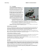
2. Site Survey
The objective of the Site survey is to find the best place to mount the antenna & the below decks equipment, the length and
routing of the cables and any other items or materials that are required to install the system and identify any other issues that
must be resolved before or during the installation. For Naval Engineering level information on this subject, please refer
to Antenna Installation Guideline – Site Arrangement, document number 130040_A available on the Sea Tel
Dealer Support Site.
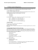
2.1. Site Selection Aboard Ship
The radome assembly should be installed at a location aboard ship where:
• The antenna has a clear line-of-sight to view as much of the sky (horizon to zenith at all bearings) as is
practical.
• The ADE should be mounted more than 5 meters (15 feet) from X-Band Navigational Radar, 10 meters (30
feet) from S-band Radar if the ADE is C-band) and appropriately farther if the radar array is high power.
• The antenna is not mounted on the same plane as the ship's Radar, so that it is not directly in the Radar beam
path.
• The ADE should be mounted more than 5 meters (15 feet) from any high power short-wave (MF/HF)
antennae.
• The ADE should also be mounted more than 4 meters (12 feet) from any short range (VHF/UHF) antennae.
• The ADE should be mounted more than 2.5 meters (8 feet) away from any L-band satellite antenna.
• The ADE should be mounted more than 3 meters (10 feet) away from any magnetic compass installations.
• The ADE should be mounted more than 2.5 meters (8 feet) away from any GPS receiver antennae.
• Another consideration for any satellite antenna mounting is multi-path signals (reflection of the satellite
signal off of nearby surfaces arriving out of phase with the direct signal from the satellite) to the antenna.
This is particularly a problem for the onboard GPS, and/or the GPS based Satellite Compass.
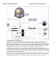
• The Above Decks Equipment (ADE) and the Below Decks Equipment (BDE) should be positioned as close to
one another as possible. This is necessary to reduce the losses associated with long cable runs.
• This mounting platform must also be robust enough to withstand the forces exerted by full rated wind load
on the radome.
• The mounting location is robust enough that it will not flex or sway in ships motion and be sufficiently well
re-enforced to prevent flex and vibration forces from being exerted on the antenna and radome.
• If the radome is to be mounted on a raised pedestal, it MUST have adequate size, wall thickness and gussets
to prevent flexing or swaying in ships motion. In simple terms it must be robust.
If these conditions cannot be entirely satisfied, the site selection will inevitably be a “best” compromise between the
various considerations.
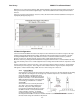
2.2. Antenna Shadowing (Blockage) and RF Interference
At the transmission frequencies of C and Ku band satellite antenna systems, any substantial structures in the way of
the beam path will cause significant degradation of the signal. Care should be taken to locate the ADE so that the ADE
has direct line-of-sight with the satellite without any structures in the beam path through the full 360 degree ships
turn. Wire rope stays, lifelines, small diameter handrails and other accessories may pass through the beam path in
limited numbers; however, even these relatively insignificant shadows can produce measurable signal loss at these
frequencies.
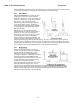
2.3. Mounting Foundation
2.3.1.
While mounting the ADE on a mast is a common solution to elevate the ADE far enough above the various
obstructions which create signal blockages, sometimes the best mounting position is on a deck or deckhouse
top. These installations are inherently stiffer than a mast installation, if for no other reason than the design of
Mounting on Deck or Deckhouse