
Installation manual

6009-33 Installation Manual Site Survey
2-2
the deck/deckhouse structure is prescribed by the ship’s classification society. In the deck/deckhouse design
rules, the minimum plating and stiffener guidelines are chosen to preclude high local vibration amplitudes.
Most installations onto a deck or deckhouse structure will require a mounting pedestal to raise the ADE above
the deck for radome hatch access and to allow the full range of elevation (see ADE mounting considerations
above). Some care must be taken to ensure the mounting pedestal is properly aligned with the stiffeners
under the deck plating.
2.3.2.
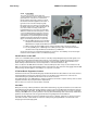
Mounting the radome directly on the deck, or platform, prevents access to the hatch in the base of the
radome unless an opening is designed into the
mounting surface to allow such entry. If there is
no access to the hatch the only way to service the
antenna is to remove the radome top. Two people
are required to take the top off of the radome
without cracking or losing control of it, but even
with two people a gust of wind may cause them to
lose control and the radome top may be
catastrophically damaged (any cracks, scratches
or other damage to the surface seal of the
tuned radome must be repaired and re-
sealed by a competent “A” layered laminate,
or cored deck, repair professional).
ADE Mounting Considerations
If access to the hatch can not be provided in the mounting surface, provide a short support pedestal to
mount the ADE on which is tall enough to allow access into the radome via the hatch.
Ladder rungs must be provided on all mounting stanchions greater than 3-4 feet tall to allow footing for
personnel safety when entering the hatch of the radome.
2.3.3.
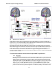
The following should be taken into account when choosing the height of a mounting support stand:
Sizing of the support pedestal
1. The height of the pedestal should be kept as short as possible, taking into account recommendations
given in other Sea Tel Guidelines.
2. The minimum height of the pedestal above a flat deck or platform to allow access into the radome
for maintenance should be 0.6 meters (24 inches).
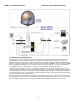
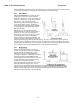
3. The connection of the ADE mounting plate to the stanchion and the connection of the pedestal to
the ship should be properly braced with triangular gussets (see graphic above). Care should be taken
to align the pedestal gussets to the ship’s stiffeners as much as possible. Doublers or other
reinforcing plates should be considered to distribute the forces when under-deck stiffeners are
inadequate.
4. The diameter of the pedestal stanchion shall not be smaller than 100 millimeters (4 inches). Where
the ADE base diameter exceeds 1.5 meters (60 inches), additional stanchions (quantity greater than
3) should be placed rather than a single large stanchion.
5. Shear and bending should be taken into account in sizing the ADE mounting plate and associated
gussets.
6. Shear and bending must be taken into account when sizing the pedestal to ship connection.
7. All welding should be full penetration welds –V-groove welds with additional fillet welds – with
throats equivalent to the thickness of the thinnest base material.
8. For an ADE mounted greater than 0.6 meters (24 inches) above the ship’s structure, at least one (1)
foot rung should be added. Additional rungs should be added for every 0.3 meter (12 inches) of
pedestal height above the ship’s structure.
9. For an ADE mounted greater than 3 meters (9 feet) above the ship’s structure, a fully enclosing cage
should be included in way of the access ladder, starting 2.3 meters (7 feet) above the ship’s
structure.
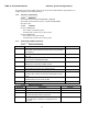
2.4. Mounting Height
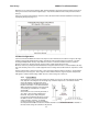
The higher up you mount the antenna above the pivot point of the ship the higher the tangential acceleration (g-
force) exerted on the antenna will be (see chart below).