
Installation manual

Site Survey 6009-33 Installation Manual
2-5
2.5.4.
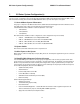
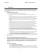
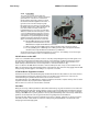
Truss masts are a variant on the girder mast
concept. Rather than a pair of columns supporting a
girder beam, the construction is a framework of
tubular members supporting a platform on which
the antennae and other equipment is mounted. A
typical truss mast is shown in this photograph.
Truss Mast
Like a girder mast, truss masts are especially stiff in
the athwart ship direction. Unlike a girder mast, the
truss can be made to be nearly as stiff in the
longitudinal direction. Truss masts are particularly
difficult to estimate the natural frequency – since a
correct modeling includes both the truss structure
of the supports and the plate/diaphragm structure
of the platform. In general, though, the following
guidelines apply when determining the adequate
support for mounting an antenna on a truss mast:
10. Antenna ADE pedestal gussets should align
with platform stiffeners which are at least
200 millimeters in depth and 10 millimeters in thickness.
11. When possible, the antenna ADE pedestal column should align with a vertical truss support.
12. For every 100 Kilograms of ADE weight over 250 Kilograms, the depth of the platform stiffeners
should be increased by 50 millimeters and thickness by 2 millimeters.
Sea Tel does not have a recommended arrangement for a truss mast – the variability of truss mast designs
means that each installation needs to be evaluated separately.
2.6. Safe Access to the ADE
Safe access to the ADE should be provided. Provisions of the ship’s Safety Management System with regard to men
aloft should be reviewed and agreed with all personnel prior to the installation. Installations greater than 3 meters
above the deck (or where the access starts at a deck less than 1 meter in width) without cages around the access
ladder shall be provided with means to latch a safety harness to a fixed horizontal bar or ring.
The access hatch for the ADE shall be oriented aft, or inboard, when practicable. In any case, the orientation of the
ADE access hatch shall comply with the SMS guidelines onboard the ship. Nets and other safety rigging under the ADE
during servicing should be rigged to catch falling tools, components or fasteners.
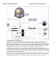
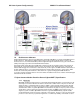
2.7. Below Decks Equipment Location
The Antenna Control Unit, Terminal Mounting Strip and Base Modem Panel are all standard 19” rack mount, therefore,
preferred installation of these items would be in such a rack. The ACU mounts from the front of the rack. The
Terminal Mounting Strip and Base Modem Panel mount on the rear of the rack.
The Satellite Modem, router, VIOP adapter(s), telephone equipment, fax machine, computers and any other associated
equipment should also be properly mounted for shipboard use.
Plans to allow access to the rear of the should be considered.
2.8. Cables
During the site survey, walk the path that the cables will be installed along. Pay particular attention to how cables will
be installed all along the path, what obstacles will have to have be routed around, difficulties that will be encountered
and the overall length of the cables. The ADE should be installed using good electrical practice. Sea Tel recommends
referring to IEC 60092-352 for specific guidance in choosing cables and installing cables onboard a ship. Within these
guidelines, Sea Tel will provide some very general information regarding the electrical installation.
In general, all cables shall be protected from chaffing and secured to a cableway. Cable runs on open deck or down a
mast shall be in metal conduit suitable for marine use. Cables passing through bulkheads or decks shall be routed
through approved weather tight glands.