
Installation manual


6009-33 Installation Manual Setup – Home Flag Offset
8-4
8.2. Mechanical Calibration of Relative Antenna Position (Home Flag Offset)
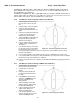
During initialization, azimuth drives the antenna CW until the Home Flag Switch senses the trailing edge of the metal
tab (as shown in the left picture above). The sensor will appear to go past the metal tab, then come back to the
trailing edge of the metal tab and stay there. This “home” position orients the pedestal to the “BOW” reference in the
radome which is directly forward of the entry hatch in the radome base. The Home Flag signal into the PCU “presets”
the relative position counter to the value stored in the Home Flag Offset (default value saved in the PCUs is 000).
This assures that the encoder input increments and decrements from this initialization value, therefore, does not have
to be precision aligned.
The metal Home Flag tab is mounted in a nylon clamp assembly. The nylon bolt/nut can be loosened to rotate the
clamp around underneath the power ring. (as shown in the center picture above).
In the simplest scenario, if you could rotate the antenna pedestal to be in-line with the bow and then rotate the home
flag clamp assembly around until the trailing edge is centered on the body of the home flag sensor, and tighten the
clamp HFO would be set close enough for “Optimizing Targeting” procedure to be effective. Unfortunately, rarely is
the equipment going to align where the clamp and sensor will be easy to access, reach and see, to align it this way.
The hex bolt heads in the plate below the Home Flag Clamp assembly are 60 degrees apart (as shown in the picture
on the right above) and allow multiple points of view to calibrate rotation of the clamp to.
If you installed the ADE with the “Bow” reference of the radome oriented in-line with the bow, the antenna pedestal
will be pointed in-line with the ships bow when stopped at the Home Flag position on completion of initialization
(before it targets a satellite) as shown in Figure 1 in the Electrical Calibration Procedure above. In this case, when the
antenna stops at the home flag and is pointed in-line with the Bow, Home Flag Offset (HFO) should be set to zero and
mechanical position of the metal Home Flag tab should be left at the 0° (default) position. Any small mechanical
mount error will be compensated when “Optimizing Targeting” is accomplished to correct for small variations of up to
+/- 5.0 degrees.
If the ADE is installed with the “Bow” reference of the radome oriented 45° to starboard the pedestal, when at home
flag position, will be pointed 45° CCW of the bow (at relative 315° as shown in Figure 2 in the Electrical Calibration
Procedure above). To compensate for this, loosen the home flag clamp, rotate the trailing edge of the metal home flag
tab CW 45° and tighten the clamp bolt (use caution not to tighten too much and strip the nylon hardware)..
You will have to estimate this 45° rotation based on the 60° spacing of the hex bolt centers. Re-initialize the antenna
and verify that when at home flag position it is pointed in-line with the ships bow. Do NOT change the Home Flag
Offset value saved in the PCU, small variations will be compensated for when “Optimizing Targeting” is
accomplished.
If the ADE is installed with the “Bow” reference of the radome oriented 90° to port, the pedestal when at home flag
position, will be pointed 90° CW of the bow (at relative 090° as shown in Figure 3 in the Electrical Calibration
Procedure above). To compensate for this, loosen the home flag clamp, rotate the trailing edge of the metal home flag
tab CCW 90° and tighten the clamp bolt (use caution not to tighten too much and strip the nylon hardware)..
You will have to estimate this 90° rotation based on the 60° spacing of the hex bolt centers. Re-initialize the antenna
and verify that when at home flag position it is pointed in-line with the ships bow. Do NOT change the Home Flag
Offset value saved in the PCU, small variations will be compensated for when “Optimizing Targeting” is
accomplished.