
Installation manual

Setup – Blockage & RF Radiation Hazard Zones 6009-33 Installation Manual
10-3
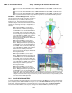
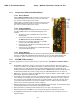
EXAMPLE 2 - Three blockage Zones, Dual Antenna
configuration: A ship has 2 Sea Tel antennas, “Antenna
A” mounted on the port side and “Antenna B” mounted on
the starboard side. Antenna A is designated as the master
antenna and its zones would be set as in example 1 above.
The mast forward, Antenna A to port and the engine
exhaust stack aft form the three zones where satellite
signal is blocked from Antenna B. The SW2 logic output
from Antenna A (ACU A) and Antenna B (ACU B) are used
to control a “Dual Antenna Arbitrator”, which will route
satellite signal from the un-blocked antenna to the other
below decks equipment. If both antennas are tracking the
same satellite, they will not both be blocked at the same
time. The logic output will switch to provide satellite signal
to the below decks equipment from Antenna A when it is
not blocked and will switch to provide satellite signal
from Antenna B whenever Antenna A is blocked. The
switches will not change state if both antennas are
blocked, or if both are on satellite.
Antenna A is the same as the previous example and
its ACU would be set to those AZ LIMIT values.
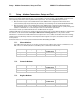
Antenna B ACU would be set to:
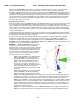
In this example Antenna B zone 1 is caused by the stack, zone 2 is from Antenna A, zone 3 is from the mast and zone
4 is not needed.
ZONE 1 begins (AZ LIMIT 1) at 188 degrees Relative and ends (AZ LIMIT 2) at 204 degrees Relative. Multiply
these Relative positions by 10. Enter AZ LIMIT 1 value of 1880 and AZ LIMIT 2 value of 2040. In this case
the stack height only causes blockage up to an elevation of 42 degrees, so we set EL LIMIT 12 to 0420. If the
antenna is between these two AZ Limit points but the elevation is greater than 42 degrees, the antenna will
no longer be blocked.
ZONE 2 begins (AZ LIMIT 3) at 254 degrees Relative and ends (AZ LIMIT 4) at 278 degrees Relative. Multiply
these Relative positions by 10. Enter AZ LIMIT 3 value of 2540 and AZ LIMIT 4 value of 2780. In this case
the Antenna B height only causes blockage up to an elevation of 12 degrees, so we set EL LIMIT 34 to 0120.
If the antenna is between these two AZ Limit points but the elevation is greater than 12 degrees, the antenna
will no longer be blocked.
ZONE 3 begins (AZ LIMIT 5) at 342 degrees Relative and ends (AZ LIMIT 6) at 348 degrees Relative. Multiply
these Relative positions by 10. Enter AZ LIMIT 5 value of 3420 and AZ LIMIT 6 value of 3480. In this case
the mast height only causes blockage up to an elevation of 41 degrees, so we set EL LIMIT 56 to 0410. If the
antenna is between these two AZ Limit points but the elevation is greater than 12 degrees, the antenna will
no longer be blocked.
ZONE 4 is not needed. Enter AZ LIMIT 7 value of 0000 and AZ LIMIT 8 value of 0000. Set EL LIMIT 78 to
0000. If your ACU software includes 5 volt polarization you will not see these AZ & EL LIMIT parameters.
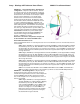
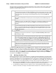
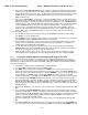
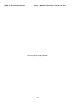
EXAMPLE 3 - One blockage Zone: A ship has a Sea Tel
antenna mounted on the center line of the ship. A mast is
forward and an engine exhaust stack is aft. In this example the
Stack does NOT block the satellite, only the mast forward
does. In this example zone 1 is caused by the mast, zone 2, 3
and 4 are not needed:
ZONE 1 begins (AZ LIMIT 1) at 352 degrees Relative
and ends (AZ LIMIT 2) at 8 degrees Relative. Multiply
these Relative positions by 10. Enter AZ LIMIT 1
value of 3520 and AZ LIMIT 2 value of 0080. In this
case the mast height only causes blockage up to an
elevation of 52 degrees, so we set EL LIMIT 12 to
0520. If the antenna is between these two AZ Limit
points but the elevation is greater than 52 degrees,
the antenna will no longer be blocked.