
Installation manual

6009-33 Installation Manual Setup – Blockage & RF Radiation Hazard Zones
10-4
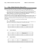
ZONE 2 is not needed. Enter AZ LIMIT 3 value of 0000 and AZ LIMIT 4 value of 0000. Set EL LIMIT 34 to
0000.
ZONE 3 is not needed. Enter AZ LIMIT 5 value of 0000 and AZ LIMIT 6 value of 0000. Set EL LIMIT 56 to
0000.
ZONE 4 is not needed. Enter AZ LIMIT 7 value of 0000 and AZ LIMIT 8 value of 0000. Set EL LIMIT 78 to
0000. If your ACU software includes 5 volt polarization you will not see these AZ & EL LIMIT parameters.
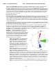
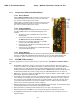
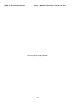
EXAMPLE 4 - Overlaid Blockage Zones: A ship has a
Sea Tel antenna mounted on the center line of the ship. A
mast mounted on top of a deckhouse (like the picture
below) is forward and an engine exhaust stack, also on a
deckhouse, is aft. These two blockage areas have wide
azimuth blockage at lower elevations and then a narrower
azimuth area of blockage extends up to a higher value of
elevation.
ZONE 1 begins (AZ LIMIT 1) at 334 degrees
Relative and ends (AZ LIMIT 2) at 026 degrees
Relative. Multiply these Relative positions by 10.
Enter AZ LIMIT 1 value of 3340 and AZ LIMIT 2
value of 0260. In this case the mast height only
causes blockage up to an elevation of 40 degrees,
so we set EL LIMIT 12 to 0400. If the antenna is
between these two AZ Limit points but the
elevation is greater than 40 degrees, the antenna
will no longer be blocked.
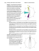
ZONE 2 begins (AZ LIMIT 3) at 352 degrees
Relative and ends (AZ LIMIT 4) at 008 degrees
Relative. Multiply these Relative positions by 10.
Enter AZ LIMIT 3 value of 3520 and AZ LIMIT 4
value of 0080. In this case the mast height only
causes blockage up to an elevation of 70 degrees,
so we set EL LIMIT 34 to 0700. If the antenna is
between these two AZ Limit points but the
elevation is greater than 70 degrees, the antenna
will no longer be blocked.
ZONE 3 begins (AZ LIMIT 5) at 155 degrees
Relative and ends (AZ LIMIT 6) at 205 degrees
Relative. Multiply these Relative positions by 10.
Enter AZ LIMIT 5 value of 1550 and AZ LIMIT 6
value of 2050. In this case the mast height only
causes blockage up to an elevation of 30 degrees,
so we set EL LIMIT 56 to 0300. If the antenna is
between these two AZ Limit points but the
elevation is greater than 30 degrees, the antenna
will no longer be blocked.
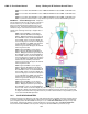
ZONE 4 begins (AZ LIMIT 7) at 173 degrees
Relative and ends (AZ LIMIT 8) at 187 degrees
Relative. Multiply these Relative positions by 10.
Enter AZ LIMIT 7 value of 1730 and AZ LIMIT 8
value of 1870. In this case the mast height only causes blockage up to an elevation of 55 degrees, so we set
EL LIMIT 78 to 0550. If the antenna is between these two AZ Limit points but the elevation is greater than
55 degrees, the antenna will no longer be blocked. If your ACU software includes 5 volt polarization you will
not see these AZ & EL LIMIT parameters.
10.2. SAVE NEW PARAMETERS
Parameters that have been changed are only temporarily changed until they are SAVED. If changes are made and not
stored, they will still be effective but will be lost when power is removed or the RESET key is pressed. Simultaneously
press, and quickly release the LEFT & RIGHT arrow keys to access “SAVE NEW PARAMETERS” directly from any other
menu display. Verify that the change(s) you have made is/are correct and then select “SAVE NEW PARAMETERS”.
Press UP arrow and then ENTER to save any recent changes into the ACUs NVRAM for permanent storage.