
Installation manual

6009-33 Installation Manual Setup – Modem Connections, Setup and Test
11-2
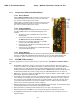
11.4. Connections (ACU to Satellite Modem)
11.4.1.
Infinity 3100 - Use an RJ-45 straight serial cable connected from the
Terminal Mounting Strip “Console Port” connector to the Console
Port connector on the rear panel of the modem.
iDirect Modems
Infinity 5100 - Use an RJ-45 straight serial cable connected from the
Terminal Mounting Strip “Console Port” connector to the Console
Port connector on the rear panel of the modem.
11.4.2.
Connect the 126877 harness assembly from the 15 pin serial port on
the 570L or 600L modem to the Terminal Mounting Strip screw
terminals.
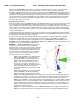
Comtech Modems
1. Assure that a jumper is installed at JP4 on the Terminal
Mounting Strip.
2. Cut the resistor/Yellow wire off of the pin on the White wire
(do NOT cut the pin off of the white wire).
3. Connect the pin on the Black & Green wire to the GND
terminal of the Terminal Mounting Strip.
4. Connect the pin on the Red wire to the SW2 terminal of the
Terminal Mounting Strip.
5. Connect the pin on the White wire to the EXT AGC terminal
of the Terminal Mounting Strip.
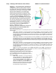
11.4.3.
A serial cable (Hughes drawing 1502273) should be provided with the modem. Connect the 15 pin to the
serial port on the HX-150 or HX-200 modem and the RJ-45 connector to the Terminal Mounting Strip
“Console Port”. Refer to instructions from your service provider for specific setting requirements.
Hughes Modems
11.5. SYSTEM TYPE parameter
The System Type parameter is used to enable a variety of system functions. The defaults in the DAC software
are:
• External AGC, or Modem Lock, function is used to bring an external modem lock signal from a satellite
modem into the ACU as a positive ID that the antenna is on the desired satellite. This input is NOT used for
Tracking purposes, it is only used during search to identify when the antenna has acquired the correct
satellite. Default external AGC function in the DAC software is disabled. Expected input is 0 VDC when the
modem has RX sync/Network Lock and a positive voltage (+15 VDC max) when the does not have lock.
• LNB Voltage - This function enables the Tracking Receiver to output 13/18 VDC to power an LNB or control a
Matrix Switch. Default for this function is OFF.
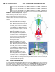
• The blockage output of the ACU is an open circuit when the antenna is not in a programmed blockage zone,
is not searching, is not targeting and is not mis-pointed by 0.5 degrees. Whenever one of these conditions
exist a transistor on the main PCB in the ACU shorts to ground providing a current sink of 0.5 amps max to
control below decks dual antenna coax switches or TX Mute control to a satellite modem (for radiation
hazard control or TX mute requirements for FCC compliance).
• Relative Azimuth value is normally only visible in the Antenna main menu display. The Azimuth entry menu
normally displays Azimuth position, DishScan tracking signal and AGC.
• When Search limit is reached the antenna will return back to the origin of the search pattern.
• When the ACU power is turned ON it does not automatically target the satellite that was used last.
• Pressing RESET on the front panel of the ACU normally only resets the processors inside but does not re-
target the satellite.