
Installation manual


6009-33 Installation Manual Setup – Modem Connections, Setup and Test
11-4
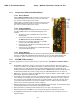
• When used as simple “RF Radiation Hazard” logic output for a single Sea Tel TX/RX antenna, this output
could be used to suppress RF transmissions while the antenna is pointed where people would be harmed by
the transmitted microwave RF power output. The SW2 output would be interfaced to the satellite modem to
disable the TX output signal from the Satellite TXRX Modem whenever the antenna is within the RF
Radiation Hazard zone(s).
• When used for “FCC TX Mute” logic output for a single Sea Tel TX/RX antenna, this output could be used to
suppress RF transmissions whenever the antenna is mis-pointed 0.5 degrees or more, is blocked, searching,
targeting or unwrapping. The SW2 output would be interfaced to the satellite modem to disable/mute the
TX output signal from the Satellite TX/RX Modem. When the mute condition is due to antenna mis-pointing,
it will not un-mute until the pointing error of the antenna is within 0.2 degrees. The default output is
contact closure to ground when the antenna is mis-pointed, therefore provides a ground to “Mute” the
satellite modem on the SW2 terminal of the Terminal Mounting Strip. If your satellite modem requires an
open to “Mute”, refer to SYSTEM TYPE parameter 16 value to reverse the output logic from the ACU.
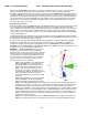
To Test the blockage function:
1. Press the NEXT key until you are at the Status menu. (Sea Tel – Remote and antenna software display)
Press ENTER to access the Tracking menu.
2. Press the RIGHT arrow key to bring up and move the cursor to the far right. Press the UP arrow to simulate a
manual BLOCKED condition. BLOCKED will appear in the Tracking display.
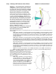
3. Verify that SW2 terminal shorts to ground (or open circuit if you have SYSTEM TYPE configured to reverse
the output logic). If the antenna is on the desired satellite and you have RX Synch, also verify that the
Satellite Modem TX is disabled/muted (TX LED OFF).
4. Press the LEFT arrow key and then press the UP arrow key to turn the simulated blocked condition OFF.
BLOCKED will disappear, leaving the ON/OFF Tracking status and the band selection in the Tracking display.
Press the UP arrow key again if you wish to toggle the Tracking state.
5. Verify that SW2 terminal is open circuit (or ground if you have logic reversed). If the antenna is on the
desired satellite and you have RX Synch, also verify that the Satellite Modem TX is enabled (TX LED ON).
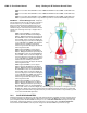
11.7. Testing the Satellite Modem Lock (Network ID) Input in the ACU
The input connections from the modem can be tested by selecting the external AGC input and monitoring the
displayed value. To test the external AGC, set the tuning frequency to 0000. Normally, AGC readings below 800 are
considered a low condition and indicate modem lock and AGC readings above 800 are considered a high condition
and indicate modem unlock.
1. Verify that the satellite modem currently has RX Sync (RX Sync LED ON).
2. Turn tracking OFF so that the antenna stays pointed ON satellite.
3. Press NEXT until the Satellite menu is displayed. Press ENTER 3 times to display the Frequency entry
window. Record the frequency that the tracking receiver is currently tuned to. Press LEFT or RIGHT arrow
key to bring up the cursor under the units digit Use the UP or DOWN arrow keys to increment or decrement
the selected digit, use the LEFT arrow key and the UP or DOWN arrow keys to change the next digit.
Continue until frequency is set to 0000. Press the ENTER key to tune the tracking receiver to this frequency.
4. View current ON satellite LOCKED AGC value in the lower right corner of the display and measure the DC
Voltage from EXT AGC (+) terminal to the GND (-) terminal. The iDirect & Comtech modems should have an
AGC readings below 800 (LOCK = low condition) and 0 VDC across the EXT AGC and GND terminals. The
Hughes modem will have an AGC reading above 800 (LOCK = high condition) and 12VDC across the EXT AGC
and GND terminals.
5. Disconnect the RXIF input coax from the rear of the satellite modem. It should lose RX Synch (RX Synch LED
OFF).
6. View current ON satellite UN-LOCKED AGC value in the lower right corner of the display and measure the
DC Voltage from EXT AGC (+) terminal to the GND (-) terminal. The iDirect & Comtech modems should have
an AGC readings above 800 (UN-LOCKED = high condition) and about +12 VDC across the EXT AGC and GND
terminals. The Hughes modem will have an AGC reading below 800 (UN-LOCKED = low condition) and
12VDC across the EXT AGC and GND terminals.
7. Reconnect the RXIF input coax to the rear of the satellite modem. It should regain RX Sync (RX Sync LED
ON).
8. Press LEFT or RIGHT arrow key to bring the up the cursor under the units digit Use the UP or DOWN arrow
keys to increment or decrement the selected digit, use the LEFT arrow key and the UP or DOWN arrow keys